Download
1 / 56
560 likes | 769 Vues
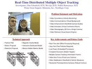
Communications & Tracking Plan Development Workshops July 9, 11 & 13 2007. Communication Reality. WV SB 247 and the Miner Act did not revoke the laws of physics. WV § 56-4 drafted with all the laws in mind. WV § 56-4. Wireless – miner not connected by wire

E N D
Communications & Tracking Plan DevelopmentWorkshopsJuly 9, 11 & 132007
Communication Reality WV SB 247 and the Miner Act did not revoke the laws of physics WV §56-4 drafted with all the laws in mind
WV §56-4 • Wireless – miner not connected by wire • Two-way communications to each miner in at least two separate airways • Tracking each miner in relation to known points prior and in escapeways after • Operators submit Communication/Tracking Plan by July 31, 2007 • Understand needs and thought through risks • Survive accident or be quickly repairable • Communication center operator min. red-hat
Electro-Magnetics for Miners Enough so you can ask the right questions … not so much it hurts your head
Frequencies Wave Lengths & Rates Analog Digital Baud Rate = Number of clock cycles per second Bit Rate = Number of bits transmitted per second
Practical options are limited by physics and existing uses ELF-LF MF WiFi VHF-UHF Available Frequencies
Bandwidth • Analog bandwidth is frequency range • Digital bandwidth is amount of information in a given amount of time Voice = 300-3400 Hz Analog bandwidth = 3100 Hz Digital bandwidth = 18,600 bps
Decibels (dB) • Decibels are measure of signal and noise Gain is given by: #dB = 10 log10 Pout Pin • When negative means loss
Losses in Wires and Cables Metal Wires & Cable Fiber Optic Cable Resistance + Skin Affect Material Absorption Splice Losses Material Scattering Bending Losses
Losses in the Entry • Path loss • Increase as square of the distance • Other Losses • Materials • Multi-path
Material Effects RF-lucent lets radio waves pass through it without any substantial loss RF-absorbent allows radio waves to pass but with substantial loss RF-opaque blocks, reflects, and scatters RF waves
R= Reflection D= Diffraction S=Scattering Multi-Path Propagation R S D
Reflective Effects Reflected waves interact to form new patterns These may not be recognized by the receiver as useful information
Ideal Waveguide Effects Confines and guides path of electromagnetic wave X 2nd 1st Y 8th
Reflective losses and absorption increase attenuation dB modes Realistic Waveguide Effects
Distortion Noise Effects • All communications systems have noise • Radio frequency interference (RFI) • Electromagnetic interference (EMI) • Laser noise Masking
Antenna Choices Antenna design offers many coverage pattern options Critical that the correct one is used for each location
Leaky Feeder Antennas Propagated Signal Internal Propagation Internal Wire Outside Sheath w/openings
Transmission Modes • Simplex • One direction • Half duplex • Either direction, but only one way at a time • Full duplex • Both directions at the same time
Software matches Tag ID database RFIDRadio Frequency Identification Radio command signal issued from reader Antenna Reader Tag holds unique ID 164B28F34 Signal containing data returned
Types of Tags • Passive • Power scavenged from reader • Active • Transmitter/ battery in tag UHF (850 MHz to 950 MHz) – Ranges to 3 meters and high reading speeds HF (13.56 MHz) – Ranges to 1.5 meters - not susceptible to interference from water or metal
Through The Earth (TTE) 200Hz-4000Hz Current Reality Commercial One-Way w/Text Off-Axis Reception Problematic Large Antenna Loops Non-Permissible Power Levels Emergency Shelter Option Greatest Potential No In-Mine Backbone
Current Reality Prototype Demonstrated Unknown Safety Medium Frequency (MF) 300 kHz - 3 MHz CABLE BELT GreatestPotential Use Existing Metal as Backbone Interoperability
Current Reality Initial units demonstrated Limited Node-to-Node Range Line-of-Sight Only Handsets not yet commercial Requires Redundancy & Hardening Wi-Fi Mesh Nodes 2.4 GHz GreatestPotential Wide Bandwidth Flexibility Interoperability NODE
Leaky Feeder (VHF) 150-170 MHz Distributed Antenna System LEAKY FEEDER Current Reality Multiple Installations Commercial Handsets Limited Beyond Sight of Feeder Limited Data Capability Requires Redundancy & Hardening AMPLIFIER Greatest Potential Available and Upgradeable Interoperability
Leaky Feeder (UHF) 400-500 MHz Distributed Antenna System LEAKY FEEDER Current Reality Multiple Installations Commercial Handsets Some Beyond Sight of Feeder Moderate Data Capability Requires Redundancy & Hardening AMPLIFIER GreatestPotential Available and Upgradeable Interoperability
Current Reality Limited Installation Experience Some Needed Devices in Prototype Leaky Feeder Enhancements Distributed Antenna System SPECIALTY ANTENNA RADIATING CABLE EXTENSION 2ND LEAKY FEEDER RUN GreatestPotential Mine Wide Coverage Multiple Pathways
Future Technologies = Survivability Current Reality Standard Telecom Practice Site Specific Best Solution Interoperability Limited Device Development Required Adoptable to Current Technology GreatestPotential Multiple Pathways System Integration Signal Takes Whatever Survives
Know the Location Proximity signal strength Acknowledgement Communicate the Location Dedicated backbone Shared backbone Show Information Map display Data analysis Threshold alarms Tracking Where GPS Won't Go Current Reality Zone Systems RFID Active Tag Systems Ethernet Backbone and Leaky Feeder Backbone Signal Triangulation Near
WV §56-4 Functionality Reviews After the evaluation of the documentation submitted and with the recommendation of our technical reviewers the Office of Miner’s Health Safety and Training verifies that _________ hasdemonstrated functionality such as would allow W.Va. underground mining permit holders to meet all or part of their requirements for emergency communications and trackingoutlined in the West Virginia Emergency Rule Governing Protective Clothing And Equipment, §56-4-8 and will be included in the listing of reviewed devices. Pre-Application Meeting Application Received Reviewed Data Augmentation Requested Re-Reviewed Functionality Determination Letter MSHA IS Approval
Varis Communications 150-170MHz Leaky Feeder Kenwood Radios Digital – 56kbs Hughes Supply 150-170MHz Leaky Feeder 400-500Mhz Leaky Feeder Kenwood Radios Digital – 56kbps Marco North-America 900MHz RFID Tracking Leaky Feeder or Ethernet Hannah Engineering 2.4GHz 802.11 Nodes VoIP Phones and WiFi Tags Digital – 11mbps Matrix Design Group 433 MHz Tag Tracking Fiberoptic Ethernet Backbone Leaky Feeder Backbone Helicomm, Inc (Venture Development) 2.4GHz 802.15.4 Nodes RS845 Ring of Subnet Controllers Digital 250kbs Text Messaging 400-500Mhz RFID Tracking Active Control Technology 2.4GHz 802.11 Nodes VoIP Phones and WiFi Tags Digital 11mbps 2.4Ghz Signal Strength Tracking MineComm (Pyott Boone Electronics) 150-170MHz Leaky Feeder 400-500Mhz Leaky Feeder Kenwood Radios Digital – 56kbps Mine Site Technology (CSE) 150-170MHz Leaky Feeder LF Through the Earth 2.4GHz 802.11 Tag Tracking Mine Radio System 150-170MHz Leaky Feeder Kenwood Radios Digital – 56kbps Ranjant Corporation 2.4 GHz 802.11 Nodes Wireless Backbone Only Northern Lights 2.4GHz 802.11 Nodes Fiber or CAT5 Ethernet Backbone WiFi Tags and VoIP Phones Active Applications
Accepted Reception Reporting Systems Adapted a standard reporting format from ARRL Quality of Communications Can you hear me now?” “ Turns out not to be a trivial question Copyright Verizon
Quality of Reporting Reporting has been done in distances Provides limited information Adopted minimal information requirements for reporting Example of tabular reporting
Ability to Relate Still need more information to make design decisions
Developing Your Plan • Operators to perfect system design • Miners to understand how the systems work • Mine Inspectors to ensure adequate coverage • Mine Rescue to understand how to contact and track in an emergency Intended to be used by: Our Plan
Why Write a Plan • To organize your thoughts and identify gaps • To provide guidance to those that implement your plan • Miners and emergency responders • Contractors • To demonstrate that you have chosen a workable solution • No points off for grammar or spelling Our Plan
Tab 2 Tab 3 Tab 4 Tab 5 Tab 1 Emergency Contact Information 39 Our Plan
Emergency Contact Information Mine Name Mine Address Physical Location Mine ID – State Mine ID – MSHA General Manager/Superintendent Name Daytime Phone # Emergency Phone # Email address Safety Manager/Director Daytime Phone # Emergency Phone # Email address Communication System Manufacturer Communication System Vendor Emergency Phone # Email address Tracking System Manufacturer Tracking System Vendor Emergency Phone # Email address Our Plan
Tab 2 Tab 3 Tab 4 Tab 5 Tab 1 Communication-Tracking System Description 41 Our Plan
Description • Overview of structure and operations of the final separate or integrated communication/ tracking system(s) • Including actions you have or will have to take to meet §56.4 requirements • Text description of the components that are currently in place and those that are planned to be added • How each contributes to meeting the requirements Our Plan
Coverage • Explain how your plan will allowing for wireless tracking and wireless two way communications with each miner providing coverage in at least two separate air courses, at least one of which shall be an intake. • And for knowing the location of miners and direction of travel at key points in the escapeways, at a minimum at junctions (section, section-submain/mains intersections), so that all options of travel are covered. Our Plan
Survivability • Explain what has been or will be done to ensure survivability such that the communication-tracking system will be functional after an accident • What provisions are made for rapidly re-establishing coverage • Maintain communication/tracking after loss of outside power Our Plan
Shelter(s) • Description of the communication system that is or will be used in shelters • Provisions made to rapidly reestablish communication if lost in the accident Our Plan
Tab 3 Tab 2 Tab 4 Tab 5 Tab 1 Communication-Tracking System Operations 46 Our Plan
Installation and Maintenance • Explain how the communications/tracking system will be: • Installed (who and how) • Tested (who and how) • Maintained (who and how) • Provide the manufacturer’s checklists for each type of inspection, routine, relocation, annual, etc Our Plan
Operating Instructions • Provide copies of the operating instructions for each component of the communication-tracking system to be provided for the miner and for emergency personnel Our Plan
Comm Center Operations • Describe the communication center • Include procedures for communication center operators covering at least: • Monitoring at all times when one or more miners are underground • Knowing the location of all miners, in relation to pre-determined points • Check-in and check-out procedures for seldom used areas • Emergency response actions Our Plan
Tab 2 Tab 3 Tab 4 Tab 5 Tab 1 Proof of order and compliance dates 50 Our Plan