Download
1 / 23
230 likes | 235 Vues
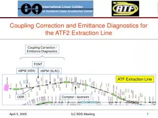
EMMA Extraction / Diagnostic line. Bruno Muratori STFC, Daresbury Laboratory. 01/09/08. EPAC08: EMMA diagnostic line. Septum is - 70 degrees Dipole to close dispersion is only 10 degrees Requirements are: Small beam Dispersion = 0 on exit of dipole

E N D
EMMA Extraction / Diagnostic line Bruno Muratori STFC, Daresbury Laboratory 01/09/08
EPAC08: EMMA diagnostic line • Septum is - 70 degrees • Dipole to close dispersion is only 10 degrees • Requirements are: • Small beam • Dispersion = 0 on exit of dipole • Difference between the two bends very large: • Introduce more quadrupoles ? • Introduce different dipoles ? • Extract at different location ?
Possible solutions Option 1: More quadrupoles Option 2: 10 degree bend → 2 × 5 degrees & more quads Option 3: Different extraction → -70 degree septum & 43 degree dipole & 4 quads
Impossible to have small beam together with a matched dispersion Number of quadrupoles appears to be insignificant in this Resulting quadrupole strengths huge ! (3 × injection) Difference in bend angles far too great Also does not work with genetic algorithm due to James Jones Can this be shown analytically ? Option1: More quadrupoles
Problem actually worsens Dispersion not closed Beta very large Dispersion very big (m) Quad strength very large Again number of quadrupoles appears to have no effect in this Therefore third option is the only option available Yet another change for the engineers to endure … Option2: Splitting the dipole & extra quads
Dispersion matched easily Betas very low Quadrupole specifications same as injection line ! Line very flexible Option3: Changing extraction point
New diagnostic line layout • Additional length → could re-use six SRS quadrupoles ! • Rest of line unchanged • Still have • Tomography • Space for possible deflecting cavity • EO section
tomography EO spectrometer Diagnostic line (1)
Ease of matching & tunability of line should be reflected in control room … (I hope !) Extra room for all the diagnostics which may be required for any eventual upgrades Betas remain very low Deflecting cavity may be located in optimum position (if we have it) Quadrupole strengths remain low for entire line Diagnostic line (2)
Beam quite small on screen ≥ 230 µm need good OTRs or YAGs (?) need good cameras Due to space restrictions only 3 screens 60° phase advance / screen Tomography (1)
Tomography (2) • Example taken from FLASH (45° phase advance / screen) courtesy Ch. Gerth
Measurements • Energy • First dipole & spectrometer at end with OTRs • Projected transverse emittance • Quadrupole scans & tomography 60° phase advance / screen • Equivalent set-up in injection line for comparisons • Bunch length • EO monitor downstream of the tomography section • No profile information • Possibility of introducing a transverse deflecting cavity (TDC) to measure additional bunch properties
deflecting voltage z σz screen deflector bunch L TDC Resolution (1) • In absence of quadrupoles resolution increases with distance (L) from TDC to screen
deflecting voltage z σz screen deflector bunch TDC Resolution (2) • In the presence of interspersed quadrupoles this is not so and we must take into account of the entire transfer matrix from TDC to screen – there can be as many quadrupoles as desired
Transverse deflecting cavity (1) • Transfer Matrix to screen gives • Transverse displacement on screen is βd – deflector, βs – screen • Want R12 big → sinΔψ = 1, βs fixed → make βd large • Beam size on the screen
deflecting cavity tomography EO spectrometer Transverse deflecting cavity (2)
deflecting cavity tomography EO spectrometer 1.6 1.35 1.13 0.95 Δµy = 65° Δµx = 90° Transverse deflecting cavity (3)
Transverse deflecting cavity (4) • Reverse of formula gives requirement of cavity voltage • Take Δµ = 65° and φ = 0 • For streaked bunch to be comparable to un-streaked bunch • βx,y = 9 m at the deflecting cavity therefore we need, assuming an emmitance degradation to 10 µm and a bunch length of 4 ps eV0 ≥ 0.23 MV @ 1.3 GHz • Equality gives a streaked beam which is √2 times un-streaked beam • only rough idea of requirements • not enough for ≥ 10 slices (what we would like) → ~ 1 MV ? • longer bunch lengths / better emittance → lower voltage
Measurements with TDC • Slice emittance & transverse profiles given by • knowledge of R12 from TDC to screen • one dimension on screen gives slice emittance • other dimension gives bunch length • Slice energy spread given by • streaked beam and spectrometer
Longitudinal slices ~250 μm Slice emittance measurements @ FLASH • R matrix from TDC to screen known • Only need width at screen → slice emittance • Bunch length given by knowledge of kick courtesy Ch. Gerth
Energy spread measurements Energy Head Unstreaked bunch Tail Time courtesy Ch. Gerth
Energy spread measurements (FLASH) • FLASH operation at 650 MeV courtesy Ch. Gerth
Conclusions / Discussion • Nice solution at long last … (Thursday of last week ) • Beam very small throughout line • Lots of tests still to be done but looks very flexible & workable • Steerers / correctors still to be included • Matching much easier than used to be (plus it works ! ) • Indication that this should be better during operation as well • Good characterisation of the beam at injection & extraction even without TDC • Have good location for TDC should it be used in the future • Realistic voltage parameters • Extra beam properties not available with EO • Currently looking at requirements for TDC with RF engineers