Download
1 / 19
190 likes | 397 Vues
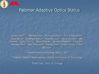
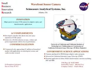
SciMeasure Wavefront Sensor Cameras and their Application in the 5m Palomar Adaptive Optics System. SciMeasure Analytical Systems, Inc. Ray DuVarney, Charlie Bleau, Garry Motter. Emory University, Department of Physics Ray DuVarney*.

E N D
SciMeasure Wavefront Sensor Camerasand their Application in the5m Palomar Adaptive Optics System SciMeasure Analytical Systems, Inc. Ray DuVarney, Charlie Bleau, Garry Motter Emory University, Department of Physics Ray DuVarney* * has a financial interest in SciMeasure Analytical Systems, Inc. NASA/JPL, Palomar AO Team Rich Dekany, Mitch Troy, Gary Brack
Camera System Overview RS-170 Video Data Out 4 12-bit Data Ports Overflow/handshake Port (SOF/SOL/DRDY) SEQUENCER RS-232 Control FIBER COMM & DATA REALTIME DISPLAY GRAPHICS DISPLAY Halt Signal VIDEO OVERLAY DATA CAPTURE Stopped Status Camera Control Unit 1.2 Ghz Bi-directional Control/data Fiber-optic Link Clocks +5V DIGITAL CLOCK DRIVERS PREAMPLIFIER Biases ±12V ANALOG FIBER COMM & DATA CCD TEC +24V ANALOG ANALOG PROCESSOR CCD Enclosure Power Supply Video Camera Head
Sequencer ISA Bus Inter-face Address Bus Data Bus 15 15 15 8 8 8 8 Programs Subroutines Patterns 24 Addr Mux 32K Static RAM Data Mux Addr Mux 32K Static RAM Data Mux Addr Mux 32K Static RAM Data Mux Data O/P Ext. Select & Sync 4-3 7-3 7-3 8-bit 8-bit 32-bit 11-12 8-12 8-12 Address Generator Address Generator Address Generator 50 MHz Clock
Sequencer Programming Patterns Programs define pattern read_pixel; # # t = /turbo, c = /clamp, S = sample, V = *DCAV # RG IA BS OR xxx t c S CCCC FV xx # 123 123 123 0123 0 010 010 010 000 0 1 0 1111 01 00; # 0 010 010 010 000 0 1 0 1111 01 00; # 1 010 010 010 000 0 1 0 1111 01 00; # 0 010 010 010 000 0 1 0 1111 01 00; # 0 010 010 010 000 0 0 0 1111 01 00; # 0 010 010 010 000 1 0 1 1111 01 00; # 0 010 010 010 000 1 0 1 1111 01 00; # 0 010 010 010 000 1 0 1 1111 01 00; # 0 010 010 001 000 1 0 1 0000 01 00; # 0 010 010 001 000 1 0 1 0011 01 00; # 0 010 010 001 000 1 0 1 1000 01 00; # 0 010 010 001 000 0 0 1 0100 01 00; # 0 010 010 001 000 0 0 1 1100 01 00; # 0 010 010 001 000 0 0 1 0010 01 00; # 0 010 010 001 000 0 0 1 1010 01 00; # 0 010 010 100 000 0 0 1 0110 01 00; # 0 010 010 100 000 0 0 1 1111 01 00; # 0 010 010 100 000 0 0 0 1111 01 00; # 0 010 010 100 000 0 1 0 1111 01 00; # 0 010 010 100 000 0 1 0 1111 01 00; # 0 010 010 100 000 0 1 0 1111 01 00; # 0 010 010 100 000 0 1 0 1111 01 00; # 0 010 010 100 000 0 1 0 1111 01 00; # 0 010 010 100 000 0 1 0 1111 01 00; # end define; define program 0; # 1100 Hz Nominal subroutine start_of_frame; repeat 32; subroutine read_line; end repeat; repeat 2; subroutine integrate; end repeat; end define; Subroutines define subroutine read_line; pattern send_start_of_line 1; pattern shift_line 1; pattern wait 10; pattern shift_pixel 17; pattern read_pixel 32; end define;
Fiber Link CAMERA CONTROL UNIT (CCU) DEMUX Digital Video Ports ONBOARD SEQUENCER Digital Data Ports MUX TRANS-CEIVER ONBOARD SCAN CONVERTER External Sequencer Data 1.2 Ghz Bidirectional Control/data Fiber-optic Link Gain Offset TEMP/VACUUM STATUS, ETC DEMUX CONTROL Filter MUX TRANS-CEIVER DATA CLOCKS CCD Clocks Clamp Sample CAMERA HEAD UNIT (CHU) Turbo
Preamplifier Board Clock Filters CCD Clocks A=5 CCD Peltier Pack Video Outputs Bias Filters CCD Biases 75 ohm drivers Temperature TEC Filters TEC Power
Analog Processor 1 of 4 channels Turbo HIGH SPEED SHUNT 2 Filter 2 Gain TIME CONST. 1 of 4 GAIN 1 of 4 Video A/D Data 75 ohms Clamp CLAMP 8 Offset OFFSET Sample
Data Output/Display/Capture Data Stream Data Capture Card Fiber Link Card INTERNAL SCAN CONVERTER 1 MEGAPIXEL DUAL PORT STATIC RAM ISA BUS INTERFACE ISA Bus RS-422 Realtime Data Ports DEMUX Data R REALTIME SCAN CONVERTER G STATIC RAM RS-170 Video B S Realtime Display Card
Camera Performance EEV CCD39 - 64x64 pixel frame size - Read Noise calculated from Photon Transfer curve MIT/LL CCID19 achieved 6.5 e- @ 1.1 Mpix/sec/port and 600 frames/sec
Future Camera Overview I DATA OUTPUT FIBER COMM/DEMUX Data Out/Handshake 16-bit Data Ports SOF/SOL/DRDY RS-232 Control CONTROLLER/SEQUENCER Halt Signal Stopped Status Control Unit 160 mm 3U cards 1.2 Ghz Bi-directional Control/data Fiber-optic Link POWER/BIASES Clocks CLOCK DRIVERS PREAMPLIFIER FIBER COMM/MUX Biases Power Supply CCD ANALOG PROCESSOR(S) 12, 14 or 16-bit options TEC CCD Enclosure Video Camera Head 160 mm 3U cards
Future Camera Overview II RS-232 Control DATA OUTPUT Halt Signal CONTROLLER/SEQUENCER Stopped Status Clocks POWER/BIASES 16-bit Data Ports & SOF/SOL/DRDY PREAMPLIFIER CLOCK DRIVERS Biases CCD ANALOG PROCESSOR(S) 12, 14 or 16-bit options TEC CCD Enclosure Video Power Supply Camera Head 160 mm 3U cards
PALAO Results QS Aql (HR 7486) Binary Star with 0.185" Separation AO Loop Open FWHM = 1.2" AO Loop Closed FWHM = 0.097" (Strehl = 20%)
PALAO Results Trapezium Cluster in the Orion Nebula The left image was taken with the AO system off; the seeing was about 1 arcsec. With the AO system locked on Theta 1 Ori C (brightest star), the stellar images were about 0.2" across, with the brightest stars saturated. Each image is represents approximately 40 arcsec x 40 arcsec field.
Acknowledgements • SBIR Phase I Grant NAS8-97195 • SBIR Phase II Grant NAS8-98081 • Jim Beletic and the ESO Optical Detector Team • Mike Shao - Director, Interferometry Center of Excellence, NASA/JPL • Eric Bloemhof - Mt. Palomar Observatory • Horace Dale - Physics Dept, Emory University