Download
1 / 17
170 likes | 378 Vues
Project X: 8 GeV Transfer and Injection Injection Painting Kick-off meeting. Dave Johnson APC/HINS June 27, 2008. Beams-doc 3129. Project X Requirements. From Project X RD&D Plan presentation, May 28, 2008 – Dave McGinnis. ->2.8E14 protons/sec. ->1.5E15 protons/sec.

E N D
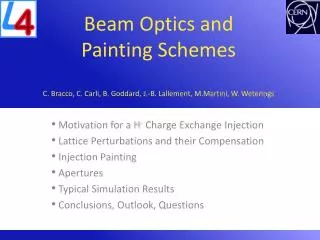
Project X: 8 GeV Transfer and Injection Injection PaintingKick-off meeting Dave Johnson APC/HINS June 27, 2008 Beams-doc 3129
Project X Requirements From Project X RD&D Plan presentation, May 28, 2008 – Dave McGinnis ->2.8E14 protons/sec ->1.5E15 protons/sec • Baseline Linac running @ 5Hz and 9mA avg. current 1ms pulse length • delivers 5.6E13/pulse at 51 kW/pulse -> 2.8E14/sec for 360 kW • For neutrino program: MI cycle of 1.4 sec -> 3 linac pulses ->1.7E14 for 154 kW at 8 GeV and 2.3MW at 120 GeV (4 linac pulses left over i.e. 200 kW @ 8 GeV • Upgrade paths • increase linac pulse length 1ms -> 3 ms • linac average current 9 mA -> 27 mA • linac rep rate 5 Hz, 10Hz, 15 Hz ??? • Example: 10Hz at 25 mA still 1ms -> 1.56E14/pulse yields 2 MW (1.56E15) at 8 GeV • Scenarios: Inject/Extract each linac cycle (1 pulse to Recycler , 9 pulses elsewhere?)
Project X RD&D Program Goals From Project X RD&D Plan presentation, May 28, 2008 – Dave McGinnis • The goal of the Project X RD&D program is to provide support for a Critical Decision 1 (CD-1) in 2010, leading to a CD-2/3a in 2011. • Design and technical component development; • Development of all project documentation mandated by DOE 413.3; • Formation of a multi-institutional collaboration capable of executing both the R&D plan and the provisional construction project. • The primary technical goal is completion of a Conceptual Design Report, followed by a fully developed baseline cost estimate and schedule, and supported by a technology development program. • Capability of delivering in at least 2 MW of beam power over the range 60 – 120 GeV, simultaneous with at least 200 kW of beam power at 8 GeV. 3
Project X RD&D Plan for FY08 From Project X RD&D Plan presentation, May 28, 2008 – Dave McGinnis Refine conceptual design where an initial cost estimate could be started this fall working toward a CD0 next spring • The main goal for the Project X RD&D Plan for FY08 is • to get an initial cost estimate for Project X for CD0. • Begin on long-term R&D items • To prepare an initial cost estimate for CD0, the design of Project X must be further developed. • To organize the labor resources in FY08, each level 2 manager reviewed the FY08 goals formulated in the RD&D plan. See http://projectx.fnal.gov/RnDplan/index.html • The basic scheme of Project X is: • An 8 GeV Linac operating at ILC-like parameters • H- stripping and proton accumulation in the Recycler • Beam distributed to the Main Injector for acceleration to 120 GeV • Beam distributed to an 8 GeV slow spill program • The major components that comprise Project X are: (Task groups) • A front end linac operating at 325 MHz (max energy 600MeV). • An ILC-like linac operating at 1300MHz. • An 8 GeV transfer line and H- Injection system. See next slide • The Recycler operating as a stripping ring and a proton accumulator. • The Main Injector acting as a rapid cycling accelerator. • A slow extraction system from the Recycler. • 120 GeV Neutrino beam line. • Civil Construction and Utilities • Controls • Cryogenics 4
Project X FY08 Goals for 8 GeV Injection From Project X RD&D Plan presentation, May 28, 2008 – Dave McGinnis • Create a viable Recycler injection straight section and transport line interface to the injection straight section and injection absorber. Integrate solutions with the new Recycler ring lattice. • Revise Proton Driver Injection absorber design for Project X beam parameters. • Initialize simulations for transverse phase space painting. • Evaluate the stripping efficiency, losses, impact on circulating beam, and technological feasibility of carbon foil stripping and laser stripping techniques for 98% to 99% stripping efficiency utilizing Project X beam parameters. • Begin Conceptual Design of transverse collimation absorbers Note: that there is/will be some overlap between topics in items 3 and 4. 5
Intensities and Scenarios • Base line design • Linac 9mA average current with 1 ms pulse length 5.6e13/pulse is 72 kJ/pulse -> implies ~90 turn injection • Linac running this intensity at 5 Hz is 2.8E14/sec or 360 kW injected. • For MI injection Recycler will accumulate up to 3 linac cycles for 1.68E14 protons then single turn transfer to MI • MI cycle 1.4 sec -> 7 linac cycles/MI cycle: 3 for MI and up to 4 for “others” • For 8 GeV program, inject and extract individual linac cycles ? • Assume linac emittance ~ 2.5 p we want to paint the 3 cycles to 25 p max • For individual injections/extractions paint to 8 p or 25 p ? • Upgrade to 2 MW • Increase linac average current X3? • Increase pulse length X3? • Increase rep rate X2? • 1.6E15/sec injected • How is this to be utilized? Inject/extract? Accumulation? How many pulses? • The question of whether Recycler “can handle this intensity” is to be addressed by the Recycler group. • NOTE: • the ratio of em/ei for SNS ~ 40 , JPARC ~ 36, Project X ~10 or less, depending • the ratio of Recycler acceptance to final emittance < x2 Vertical and <x3 Horizontal
Existing 8 GeV line enclosure Existing 8 GeV line New Proton Driver transport line New Proton Driver /8GeV line Enclosure Existing Main Injector MI-10 Project Layout MOMENTUM COLLIMATION TRANSVERSE COLLIMATION LINAC LINAC DUMP INJECTION ABSORBER
Option for Project X Transport Line • The upstream end of the transport line remains unchanged. The new vertical bend section moves transport line further under MI-65 (needs to be verified) collimation New section Defines beam size on foil, hence specifications for injection foil injection
Initial Recycler Lattice Modifications bx~70 Next slide ~25m by ~30 Dispersion “free” Qx=25.445 • Issue: • use phase trombone for tune control • add distributed quads for tune control Qy=24.134 No tuning !
Start paint End paint Removal from foil DC orbit (Chicane) Injection region Next slide • Layout used for Proton Driver injection into Main Injector
Thick foil H0->H+ H0 Stripping foil H- H+ to inj. absorber HBC2 HBC1 HBC3 HBC4 75 to 100 mm Circulating protons 8.941 m 1.068 m 0.606 m foil Injection layout • Layout used for Proton Driver injection into Main Injector
H- Injection Orbit Foil s11(cir) Offset s11(inj) s33(inj) s33(cir) Foil support Painting Chicane (DC Bump) B0 = maximum kick N = Number turns to paint n = turn number P = Painting displacement R = Removal displacement T = Total displacement Removal Total Start Paint 150 mm 150mm 100 mm MI CL 0 mm Current scheme • Current scheme is anti-correlated horizontal painting and vertical steering. • Suggested by KEK and implemented into STRUCT
Start injection Stripping foil End 1st injection End 2nd injection Closed orbit movement End 3rd injection Move off foil Foil (injected beam) Closed orbit Power Supply waveforms for 3 linac cycle injection • Waveform for anti-correlated H paint/ V steer
Exponential Painting Bumps for Anti-correlated painting • Bumps proposed by Joanne Beebe-Wang (BNL) for 3ms anti-correlated h paint/v steer PD injection. • X = A+Bexp(-t/t) • Y’ = A+Bexp(t/t) We would like to compare the resultant phase space, number or parasitic hits, etc. between the exponential functions and the square root functions.
Goals/Questions • We would like to investigate both correlated and anti-correlated painting • Investigate foil orientation and impact on number of circulating hits • Investigate KEK and exponential functions • Do either functional forms create a distribution close-enough to a KV distribution which minimizes • Compare results with STRUCT and ORBIT • Understand how each code treats interaction of circulating beam with foil. • What kind of field descriptions are required? • Investigate impact of space charge on resultant phase space. • Minimize number of foil hits from circulating beam • Investigate power supply requirements for injection kickers bumps
TASK: Initialize simulations for transverse phase space painting • Deliverables: • Specifications for phase space painting magnet requirements • Conceptual design of power supply for phase space painting magnets • Status report on phase space painting simulations • David Johnson • Classification: Eng. Physicist • Percent Effort: 10% • Duration 5 months • Task: Provide requirements and parameters for phase space painting. Coordinate simulations and provide initial parameters for magnet and power supply designs. • Sasha Drozhdin • Classification: Scientist • Percent Effort: 50% • Duration 4 months • Task: Make necessary code changes and implement new Recycler Ring Project X injection optics into STRUCT and initiate transverse painting simulations. • Leonid Vorobiev • Classification: Scientist • Percent Effort: 50% • Duration 4 months • Task: Make necessary code changes and implement new Recycler Ring Project X injection optics into ORBIT and initiate transverse painting simulations. • Steve Hays • Classification: Engineer • Percent Effort: 15% • Duration 2 months • Task: Generate a conceptual design for power supply system capable of creating the flexible waveforms required for transverse phase space painting.
Action Items • What do we need to do to get started? • Are the currently defined deliverables and tasks appropriate? Any modifications? • What is required to implement various painting schemes into ORBIT and STRUCT? • What kind of input phase space needs to be produced (from TRACK)? • Can the MI PD lattice be utilized while RR lattice is being developed? • Do we need to bring anyone else on board immediately? • Longevity of ORBIT support at FNAL? • Regular meetings ? Frequency? • Anything I forgot?