Download
1 / 56
560 likes | 860 Vues
Packaging and Interconnection. References. H.B.Bakoglu, ‘ Circuits, Interconnections, and Packaging for VLSI ’ , Addison-Wesley, 1990. Packaging. 1. Overview Agony of interconnection : Device becomes smaller, faster while chip size and routing length becomes bigger.

E N D
References • H.B.Bakoglu, ‘Circuits, Interconnections, and Packaging for VLSI’, Addison-Wesley, 1990
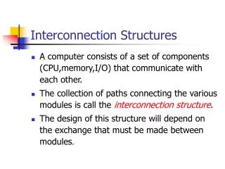
1. Overview • Agony of interconnection : • Device becomes smaller, faster while chip size and routing length becomes bigger. • IR voltage drop, delay, power dissipation due to interconnects, and max. current density, noise coupling/crosstalk are serious problems in future VLSI and now. • Typical distribution of interconnection lines. Clock, bus
2. Packaging • Package Types : 2-side : DIP(Dual In-Line) : thru-hole 4-side : QFP(Quad Flat Package) : SMT (Surface Mount Tech.) area type : PGA(Pin Grid Array) : thru-hole BGA(Ball Grid Array) • Chip to package bonding : wire bonding TAB (Tape Automated Bonding) Flip-chip bonding
Level 0 Level 1 Level 2 Level 3 • MCN(Multi-Chip Module) Level 15
MCM 제품의 형태 및 비표 • MCM-L(Laminated) : 극세선 다층구조 PCB 기판, 저가, 중성능, Cache 메모리 모듈 등 다양한 용도 • MCM-C(Ceramic) : 하이브리드 기술, 대형 컴퓨터, 군사/항공용 특수용도 • MCM-D(Deposited) : 반도체 칩 공정으로부터 파생, 구리/폴리이미드 다층구조, 컴퓨터, 정보통신, Workstation, PC, 이동전화기 등 광범위한 용도
MCM 요소 기술 • MCM 설계 기술 : 기판재료, 절연체 재료, 접착재료, PCB 재료 등 재료설계 (재료, 화공), 전기적 회로 설계(전자), 열적 냉각 설계(기계) • MCM 단위공정 기술 coating, etching, metallization, lithography 등 • 안정된 베어(bare)칩 세트 확보 • Known Good Die(KGD) 문제 : MCM Yield • MCM 테스트 기술 • Inter-disciplinary collaboration
MCM 시장 및 기술 예측(1997 년도 예상) • 1998년 MCM 시장 : $1.6 billion • MCM 시장의 큰 driver : 데이터 처리, 정보 통신(B-ISDN) (HDTV, CATV, ATM 등) 내장형 콘트롤러 (DSP, GPS, RISC 등), Workstation/PC, 이동전화기 • 저가의 MCM-L 시장 기존 PCB와 경쟁 • 고가의 MCM-D 시장 : > 100MHz
Multi-Chip Module Technique • 구조 : i) IC 칩 : 한 개 이상의 칩 실장 ii) Substrate : (열팽창계수(TCE), 유전상수, 열 전도율, 비용) • type • MCM-L : FR-4, Polyimide Glass, • MCM-D : Si, SiC, SiN, SiO2 • MCM-C : Alumina, • Hybrid MCM • Routing : 배선층, I/O 배정, 칩 배치, 고밀도 배선(via 사용) • 배선구조 : 도체 - 절연체 • 기판 - 배선(Cr/Cu-Polymer-Cu-Polymer-Cu/Au)-chip • 공정 : i) 칩 bonding(die bonding) ii) 칩과 기판 연결 : wire bonding, TAB, flip chip • 전기적 시험
MCM Package Structures Technology Thin Film Thick Film PCB (type) (MCM-D) (MCM-C) (MCM-L) A. Dielectric Polyimide/SiO2 Alumina Epoxy-Glass Glass+Ceramic Polyimide-glass Dielectric Constant Er 3.2/3.8 9-10/4-8 4.7/2.5 Resistivity(-cm) 1016/1014 1014/1014 1014/1014 Thickness(m) < 20 100 and up 100 and up B. Conductors Cu-Al W, Mo, Cu, Au Cu, Au Sheet resistance(m/sq) 3-4.2 2-15 3 Thickness(m) 10 20-30 18-35 Line width(m) 25 100 and up 70 and up Via hole size(m) 40 100 and up 50 and up Min Via Grid(m) 100 250 and up 250 and up No. of Layers 1-6 30 and up 50 C. Dielectric and Via Coat/Deposit+Litho Tape/Punch Punch/Drilling D. Conductor Sputter Screen Laminate/Deposit electroplate,Photolitho E. Firing/Curing/Arm 400 C(Oxidizing) 900C(N2) < 100C G. I/O Connection Solder Bond Solder/Braze Solder/Braze
MCM design flow • Chip placement • wiring design i) # of I/O ports, module area, wire length/layer, via • Chip placement • Electrical considerations • Electrical Design Considerations a) Key design factors : 1. Physical dimension(space) 2. Electrical consideration 3. Thermal consideration b)Information transfer process : 1. Change in the signal level 2. Signal transition time c)Electrical parameters : Requirements R- Voltage drops Faster switching speeds C- RC delays Reducing input capacitance L- delay noise Optimizing the driving impedance
Interconnection Modelling : • Modelling of interconnection line as i) lumped C model : treated as lumped capacitive loads ii) lumped RC mode : first-order consideration of R when R is significant iii) distributed RC model : better consideration of R’s (intra-chip wire) iv) transmission line model : if the interconnection wire is sufficiently long or circuits very fast s.t. signal rise time is comparable to the time of flight across the line, i.e, L is not negligible.(PCB wire) v) lossy transmission line model : (MCB substrate wire)
Interconnection wire의 전송선 modelling l : wire length : signal 의 wavelength t=l/v : time of flight t=/v : signal 의 rise time 1. t << Tr (i.e., l << )인 경우 : wire는 lumped capacitance로 model 가능 2. 그렇지 않은 경우 : 1) lossless 일 때 (R 성분이 L 성분에 비해 작을 때) : transmission line으로 model 2) lossy 인 경우 : R 성분이 L 성분보다 크므로 Transmission line효과 보다는 RC distributed 회로로 model 가능. 즉, wire R >> Zo(특성저항)인 경우
Observations 1. High-speed chip의 detailed modelling을 위해서는 pin, lead frame, bonding wire 등을 전송선으로 보고 2-D 해석을 해야 함. 2. 대략의 chip-to-chip delay 계산을 위해서는 board wiring은 전송선으로, pin, lead frame 등은 lumped C or L load로 model 하면 충분. 3. * Power ground line은 Signal line과 달리 C는 키우고 L은 줄이는 것이 좋다. ( 스위칭 noise)
Transmission line model • Lossless transmission line • Inductance of a device = V B A I I D C Magnetic flux Electric current carried (L’ and ’ are inductance, and magnetic flux per line length.)
= Similarly for C = Zo(char imp)
Reflected waveforms for inductive & capacitive discontinuity (time constant ; L/2Z, ZC/2)
Ii Ir It Vi • Magnitudes of Reflected & Transmitted components of voltage(current) wave at the transmission line discontinuity. Vr Z1 Vt Z2 Vi Vr Vt Define (reflection coeff.)= and T(transmission coeff.)= Then, from(1), T = 1+ and from(2),
Reflected waveforms at the unterminated transmission line ; V=VS /2 V-source에 의한 VG에 대한 영향 R-divider로 볼 때는 V=VS로, X-mission line으로 볼 때는 V=VS /2로 놓는다. RS=0.1 Z일때 : RS=10 Z일때 :
When Rs=10Z, Rs=Z, and Rs=0.1Z, respectively(not in the same scale)
Transmission line의 termination : i) RS=0, RL=(no termination) (dotted line : RS=0.1 Zo 일때)
Driver and termination circuits for tr. lines. i) term. at receiver end
What limits bandwidth? • Circuit speed • Impedance discontinuity • Pad capacitance • Bonding wire • Package trace • PCB trace • PLL & DLL jitter in the receiver • Wire limits
Copper vs Fiber • Copper: • Coaxial Cable, Twin-axial Cable, UTP (unshielded Twisted Pair), STP (Shielded Twisted Pair), etc. • High bandwidth over short distance • Low cost • EMI, ground isolation, interference problem • Fiber: • Multi-mode fiber (Step-index, Graded-index), Single-mode fiber • Light sources: Laser diode or LED • Material: Silica or plastic • High bandwidth over long distance • High cost • No interference, no crosstalk, no EMI • Interface with electrical signals through a limiting amplifier (TX) and a trans-resistance amplifier (RX)