Download
1 / 51
510 likes | 744 Vues
Routing. Outline Algorithms Scalability. A. 6. 1. 3. 2. F. 1. E. B. 4. 1. 9. C. D. Overview. Forwarding vs Routing forwarding: to select an output port based on destination address and routing table routing: process by which routing table is built Network as a Graph

E N D
Routing Outline Algorithms Scalability
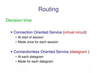
A 6 1 3 2 F 1 E B 4 1 9 C D Overview • Forwarding vs Routing • forwarding: to select an output port based on destination address and routing table • routing: process by which routing table is built • Network as a Graph • Problem: Find lowest cost path between two nodes • Factors • static: topology • dynamic: load
Distance Vector • Each node maintains a set of triples • (Destination, Cost, NextHop) • Directly connected neighbors exchange updates • periodically (on the order of several seconds) • whenever table changes (called triggered update) • Each update is a list of pairs: • (Destination, Cost) • Update local table if receive a “better” route • smaller cost • came from next-hop • Refresh existing routes; delete if they time out
B C A D E G F Example Destination Cost NextHop A 1 A C 1 C D 2 C E 2 A F 2 A G 3 A
Routing Loops • Example 1 • F detects that link to G has failed • F sets distance to G to infinity and sends update t o A • A sets distance to G to infinity since it uses F to reach G • A receives periodic update from C with 2-hop path to G • A sets distance to G to 3 and sends update to F • F decides it can reach G in 4 hops via A • Example 2 • link from A to E fails • A advertises distance of infinity to E • B and C advertise a distance of 2 to E • B decides it can reach E in 3 hops; advertises this to A • A decides it can read E in 4 hops; advertises this to C • C decides that it can reach E in 5 hops…
Loop-Breaking Heuristics • Set infinity to 16 • Split horizon • Split horizon with poison reverse
Link State • Strategy • send to all nodes (not just neighbors) information about directly connected links (not entire routing table) • Link State Packet (LSP) • id of the node that created the LSP • cost of link to each directly connected neighbor • sequence number (SEQNO) • time-to-live (TTL) for this packet
Link State (cont) • Reliable flooding • store most recent LSP from each node • forward LSP to all nodes but one that sent it • generate new LSP periodically • increment SEQNO • start SEQNO at 0 when reboot • decrement TTL of each stored LSP • discard when TTL=0
Route Calculation • Dijkstra’s shortest path algorithm • Let • N denotes set of nodes in the graph • l (i, j) denotes non-negative cost (weight) for edge (i, j) • s denotes this node • M denotes the set of nodes incorporated so far • C(n) denotes cost of the path from s to node n M = {s} for each n in N - {s} C(n) = l(s, n) while (N != M) M = M union {w} such that C(w) is the minimum for all w in (N - M) for each n in (N - M) C(n) = MIN(C(n), C (w) + l(w, n ))
Metrics • Original ARPANET metric • measures number of packets queued on each link • took neither latency or bandwidth into consideration • New ARPANET metric • stamp each incoming packet with its arrival time (AT) • record departure time (DT) • when link-level ACK arrives, compute Delay = (DT - AT) + Transmit + Latency • if timeout, reset DT to departure time for retransmission • link cost = average delay over some time period • Fine Tuning • compressed dynamic range • replaced Delay with link utilization
How to Make Routing Scale • Flat versus Hierarchical Addresses • Inefficient use of Hierarchical Address Space • class C with 2 hosts (2/255 = 0.78% efficient) • class B with 256 hosts (256/65535 = 0.39% efficient) • Still Too Many Networks • routing tables do not scale • route propagation protocols do not scale
NSFNET backbone Stanford ISU BARRNET MidNet … regional regional Westnet regional Berkeley P ARC UNL KU UNM NCAR UA Internet Structure Recent Past
Large corporation “ ” Consumer ISP Peering point Backbone service provider Peering point Consumer ” ISP “ “ Consumer ISP ” Large corporation Small corporation Internet Structure Today
Network number Host number Class B address 111111111111111111111111 00000000 Subnet mask (255.255.255.0) Network number Subnet ID Host ID Subnetted address Subnetting • Add another level to address/routing hierarchy: subnet • Subnet masks define variable partition of host part • Subnets visible only within site
Subnet mask: 255.255.255.128 Subnet number: 128.96.34.0 128.96.34.15 128.96.34.1 H1 R1 Subnet mask: 255.255.255.128 128.96.34.130 Subnet number: 128.96.34.128 128.96.34.139 128.96.34.129 H2 R2 H3 128.96.33.1 128.96.33.14 Subnet mask: 255.255.255.0 Subnet number: 128.96.33.0 Subnet Example Forwarding table at router R1 Subnet Number Subnet Mask Next Hop 128.96.34.0 255.255.255.128 interface 0 128.96.34.128 255.255.255.128 interface 1 128.96.33.0 255.255.255.0 R2
Forwarding Algorithm D = destination IP address for each entry (SubnetNum, SubnetMask, NextHop) D1 = SubnetMask & D if D1 = SubnetNum if NextHop is an interface deliver datagram directly to D else deliver datagram to NextHop • Use a default router if nothing matches • Not necessary for all 1s in subnet mask to be contiguous • Can put multiple subnets on one physical network • Subnets not visible from the rest of the Internet
Supernetting • Assign block of contiguous network numbers to nearby networks • Called CIDR: Classless Inter-Domain Routing • Represent blocks with a single pair (first_network_address, count) • Restrict block sizes to powers of 2 • Use a bit mask (CIDR mask) to identify block size • All routers must understand CIDR addressing
IP Router • Forwarding Equivalence Classes (FEC) • e.g., 172.200.0.0/16 • Forwarding table: FEC < next_hop, port > • match address to FEC with longest prefix • forward to “smarter” router by default • Core routers have ~100,000 FECs
Route Propagation • Know a smarter router • hosts know local router • local routers know site routers • site routers know core router • core routers know everything • Autonomous System (AS) • corresponds to an administrative domain • examples: University, company, backbone network • assign each AS a 16-bit number • Two-level route propagation hierarchy • interior gateway protocol (each AS selects its own) • exterior gateway protocol (Internet-wide standard)
Popular Interior Gateway Protocols • RIP: Route Information Protocol • developed for XNS • distributed with Unix • distance-vector algorithm • based on hop-count • OSPF: Open Shortest Path First • recent Internet standard • uses link-state algorithm • supports load balancing • supports authentication
EGP: Exterior Gateway Protocol • Overview • designed for tree-structured Internet • concerned with reachability, not optimal routes • Protocol messages • neighbor acquisition: one router requests that another be its peer; peers exchange reachability information • neighbor reachability: one router periodically tests if the another is still reachable; exchange HELLO/ACK messages; uses a k-out-of-n rule • routing updates: peers periodically exchange their routing tables (distance-vector)
BGP-4: Border Gateway Protocol • AS Types • stub AS: has a single connection to one other AS • carries local traffic only • multihomed AS: has connections to more than one AS • refuses to carry transit traffic • transit AS: has connections to more than one AS • carries both transit and local traffic • Each AS has: • one or more border routers • one BGP speaker that advertises: • local networks • other reachable networks (transit AS only) • gives path information
128.96 Customer P 192.4.153 (AS 4) Regional provider A (AS 2) Customer Q 192.4.32 (AS 5) 192.4.3 Backbone network (AS 1) Customer R 192.12.69 (AS 6) Regional provider B (AS 3) Customer S 192.4.54 (AS 7) 192.4.23 BGP Example • Speaker for AS2 advertises reachability to P and Q • network 128.96, 192.4.153, 192.4.32, and 192.4.3, can be reached directly from AS2 • Speaker for backbone advertises • networks 128.96, 192.4.153, 192.4.32, and 192.4.3 can be reached along the path (AS1, AS2). • Speaker can cancel previously advertised paths
IP Version 6 • Features • 128-bit addresses (classless) • multicast • real-time service • authentication and security • autoconfiguration • end-to-end fragmentation • protocol extensions • Header • 40-byte “base” header • extension headers (fixed order, mostly fixed length) • fragmentation • source routing • authentication and security • other options
4.4 Multicast Outline 4.4.1 Multicast Addresses 4.4.2 Multicast Routing (DVMRP, PIM, MSDP) Encoding
Intra domain OSPF (Open Shortest Path First) IS-IS RIP EIGRP … Inter domain BGP v4 (Border Gateway Protocol) EGP(Exterior Gateway Protocol) Autonomous System (AS) Group of networks, single administrative authority Policy and connectivity Routing protocolUnicast
Intra domain MOSPF Extension to OSPF DVMRP Distance Vector Multicast Routing Protocol The mrouted implementation (Flood & Prune) PIM Protocol Independent Multicast Routing protocol independent Sparse mode Dense mode Inter domain MBGP + MSDP Currently used BGMP + MASC Routing protocolMulticast
Addressing • Multicast group in the Internet has its own Class D address • looks like a host address, but isn’t • Class D address in IP address space are used as multicast destination address • 224.0.0.0 to 239.255.255.255, 28 bits can be used, over 250 million groups possible • Multicast address can appear only as destination address, never as source address • When sent to a multicast address, the packet reaches to all host who are currently belonging to that group
Multicast routing • Broadcast and prune (DVMRP, PIM-DM) • Reverse shortest path tree • Routers do reverse path forwarding (RPF) check • Explicit join (CBT, PIM-SM) • Receivers send join to rendezvous point (RP) • Senders send multicast data to RP, up the tree • RP fans out multicast data (its a meeting point) • Optimizations in PIM-SM to short-cut the RP • Shared tree versus source specific tree
DVMRP • DVMRP ( Distance vector multicast routing protocol) • Very similar to RIP • distance vector • hop count metric • reverse-path forwarding • Used in conjunction with • flood-and-prune (to determine memberships) • prunes store per-source and per-group information • Each router stores prune information for reverse path multicasting i.e. selective forwarding. ( per source, per group for each interface) • explicit join messages (unlike pure flood and prune) to reduce join latency (but no source info, so still need flooding)
Internet Multicast Protocol • Multicast version of OSPF • In link state each router monitors its directly connected links and broadcasts to all other routers whenever a change in link state occurs • The extension requires to support multicasting is following: -The link state part also contains all multicast groups for which the link has member(s) -with this information each router can compute the shortest path multicast tree for each source of each group • Since router has to store this tree for each source for each group, overhead is high, hence not scalable
MOSPF • MOSPF (Multicast OSPF) • Multicast extension to OSPF • Routers flood group membership information with LSPs (LSP extended) • Each router independently computes shortest-path tree that only includes multicast-capable routers • no need to flood and prune • Group joining and leaving information gets updated in all router through Link State Update • Complex • need storage per group per link • need to compute shortest path tree per source and group • Since router has to store this tree for each source for each group, overhead is high, hence not scalable
Core based tree Multicasting • DVMRP and MOSPF were source based multicast tree • Each source uses different source specific shortest path tree for data forwarding • Cost of group formation with these schemes: join/prune information store per source per group per interface in each router. • Both suffer from scaling problems.Building trees installs state in the routers. It is easy to observe that both do not scale well when a relatively small proportion (sparse mode) of routers wants to receive packet from a particular group. CBT and PIM( see next slides) are primarily for sparse mode situation.
Core based tree Multicasting • Core based Tree: Key idea with core-based tree • coordinate multicast with a core router • host sends a join request to core router • routers along path mark incoming interface for forwarding.
PIM Dense mode Flood & prune PIM Sparse mode Shared tree (Core Based Tree, CBT) Switches to SPT Root called Rendezvous Point (RP) PIM SSM Source specific multicast IGMP v3 PIM Bidir implements shared sparse trees with bidirectional flow of data PIM
Protocol independent multicast – sparse mode (PIM-SM) • Underlying unicast routing protocol is used • Receivers must explictly join groups (no flooding) • Everyone meets at a rendezvous point (RP) • RP is the core of a uni-directional tree • First hop routers encapsulate multicast to RP • RP can join source to the tree to avoid encap • State and reliability issues
Multi-protocol BGP (MBGP) • BGP extension to carry other routes (e.g multicast) • Provides for route aggregation and policy • Used between ASes • Carries information about the sources of multicast
MBGP • MBGP, Multiprotocol Extensions forBGP v4 (BGP4+), RFC 2283 • Extended BGP peering • Allows different unicast and multicast paths
MSDP • MSDP, Multicast Source Discovery Protocol • Interconnects RPs and exchanges information of active sources • Peer over TCP, sends Source Active message • Gives PIM information of how to join the source at exchange point • One entry per active source!
BGMP • Border Gateway Multicast Protocol • Each group has a predefined root (or use MASC) • BGMP builds a bi-directional, shared tree of domains • Domains can run any multicast IGP internally • Still under development http://www.ietf.org/html.charters/bgmp-charter.html
4.5 Multiprotocol Label Switching Outline 4.5.1 Destination-Based Forwarding 4.5.2 Explicit Routing 4.5.3 Virtual Private Networks and Tunnels
Internet IP LER LER LER LSR LSR LSR LSR MPLS IP MPLS Network Model MPLS LSR = Label Switched Router LER = Label Edge Router
Control: Control: Control: IP Router Software IP Router Software ATM Forum Software Forwarding: Forwarding: Forwarding: Longest-match Lookup Label Swapping Label Swapping Basic Idea • MPLS is a hybrid model adopted by IETF to incorporate best properties in both packet routing & circuit switching MPLS ATM Switch IP Router
Basic Idea (Cont.) • Packets are switched, not routed, based on labels • Labels are filled in the packet header • Basic operation: • Ingress LER (Label Edge Router) pushes a label in front of the IP header • LSR (Label Switch Router) does label swapping • Egress LER removes the label • The key : establish the forwarding table • Link state routing protocols • Exchange network topology information for path selection • OSPF-TE, IS-IS-TE • Signaling/Label distribution protocols: • Set up LSPs (Label Switched Path) • LDP, RSVP-TE, CR-LDP
1a. Routing protocols (e.g. OSPF-TE, IS-IS-TE) exchange reachability to destination networks 4. LER at egress removes label and delivers packet 1b. Label Distribution Protocol (LDP) establishes label mappings to destination network 10 20 40 IP IP IP IP IP 2. Ingress LER receives packet and “label”s packets 3. LSR forwards packets using label swapping MPLS Operation