Download
1 / 39
390 likes | 396 Vues
Trigger Systems at LHC Experiments. Institute of High Energy Physics of the Austrian Academy of Sciences`. Manfred Jeitler Instr-2008, Novosibirsk, March 2008. first particle physics experiments needed no trigger were looking for most frequent events

E N D
Trigger Systems at LHC Experiments Institute of High Energy Physics of the Austrian Academy of Sciences` Manfred Jeitler Instr-2008, Novosibirsk, March 2008
first particle physics experiments needed no trigger • were looking for most frequent events • people observed all events and then saw which of them occurred at which frequency
later physicists started to look for rare events • “frequent” events were known already • searching “good” events among thousands of “background” events was partly done by auxiliary staff • “scanning girls” for bubble chamber photographs
+30 MinBias Higgs ->4m
due to the extremely small cross sections of processes now under investigation it is impossible to check all events “by hand” • ~ 1013 background events to one signal event • it would not even be possible to record all data in computer memories • we need a fast, automated decision (“trigger”) if an event is to be recorded or not
detectors yielding electrical output signals allow to select events to be recorded by electronic devices • thresholds (discriminators) • logical combinations (AND, OR, NOT) • delays • available in commercial “modules” • connections by cables (“LEMO” cables)
1 x 400 x • because of the enormous amounts of data at major modern experiments electronic processing by such individual modules is impractical • too big • too expensive • too error-prone • too long signal propagation times • use custom-made highly integrated electronic components (“chips”) ~ 10 logical operations / module ~ 40000 logical operations in one chip
example: trigger logic of the L1-trigger of the CMS experiment
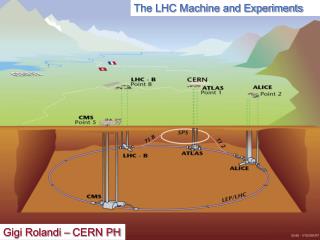
When do we trigger ? • „bunch” structure of the LHC collider • „bunches” of particles • 40 MHz • a bunch arrives every 25 ns • bunches are spaced at 7.5 meters from each other • bunch spacing of 125 ns for heavy-ion operation • at nominal luminosity of the LHC collider (1034 cm-2 s-1) one expects about 20 proton-proton interactions for each collision of two bunches • only a small fraction of these “bunch crossings” contains at least one collision event which is potentially interesting for searching for “new physics” • in this case all information for this bunch crossing is recorded for subsequent data analysis and background suppression • luminosity quoted for ATLAS and CMS • reduced luminosity for LHCb (b-physics experiment) • heavy-ion luminosity much smaller
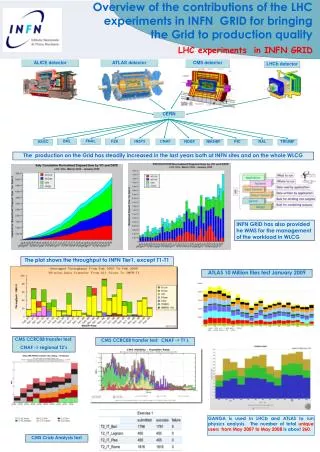
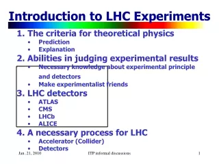
the LHC experiments • 4 major experiments • 3 different main physics goals • “general purpose”: Higgs, Susy, ..... : ATLAS+CMS • b-physics: LHCb • heavy ion physics: ALICE • different emphasis on trigger: • ATLAS+CMS: high rates, many different trigger channels • LHCb: lower luminosity, need very good vertex resolution (b-decays) • ALICE: much lower luminosity for heavy ions, lower event rates, very high event multiplicities
trigger:first level high level ATLAS, CMS 40 MHz 100 kHz 100 Hz LHCb 40 MHz 1 MHz 2 kHz ALICE 10 kHz 1 kHz 100 Hz Event size (bytes)
read write How do we trigger ? • use as much information about the event as possible • allows for the best separation of signal and background • ideal case: “complete analysis” using all the data supplied by the detector • problem: at a rate of 40 MHz it is impossible to read out all detector data • (at sensible cost) • have to take preliminary decision based on part of the event data only • be quick • in case of positive trigger decision all detector data must still be available • the data are stored temporarily in a “pipeline” in the detector electronics • “short term memory” of the detector • “ring buffer” • in hardware, can only afford a few μs • how to reconcile these contradictory requirements ?
multi-level trigger • first stage takes preliminary decision based on part of the data • rate is already strongly reduced at this stage • ~1 GHz of events (= 40 MHz bunch crossings) ~100 kHz • only for these bunch crossings are all the detector data read out of the pipelines • still it would not be possible (with reasonable effort and cost) to write all these data to tape for subsequent analysis and permanent storage • the second stage can use all detector data and perform a “complete analysis” of events • further reduction of rate: ~100 kHz ~100 Hz • only the events thus selected (twice filtered) are permanently recorded
How does the trigger actually select events ? • the first trigger stage has to process a limited amount of data within a very short time • relatively simple algorithms • special electronic components • ASICs (Application Specific Integrated Circuits) • FPGAs (Field Programmable Gate Arrays) • something in between “hardware” and “software”: “firmware” • written in programming language (“VHDL”) and compiled • fast (uses always same number of clock cycles) • can be modified at any time when using FPGAs • the second stage (“High-Level Trigger”) has to use complex algorithms • not time-critical any more (all detector data have already been retrieved) • uses a “computer farm” (large number of PCs) • programmed in high-level language (C++)
How does the trigger actually select events ? • the first trigger stage has to process a limited amount of data within a very short time • relatively simple algorithms • special electronic components • ASICs (Application Specific Integrated Circuits) • FPGAs (Field Programmable Gate Arrays) • something in between “hardware” and “software”: “firmware” • written in programming language (“VHDL”) and compiled • fast (uses always same number of clock cycles) • can be modified at any time when using FPGAs • the second stage (“High-Level Trigger”) has to use complex algorithms • not time-critical any more (all detector data have already been retrieved) • uses a “computer farm” (large number of PCs) • programmed in high-level language (C++) • see Marta Felcini’s talk tomorrow
ATLAS+CMS:what’s the difference ? • similar task • similar conditions • similar technology
ATLAS+CMS:what’s the difference ? • similar task • similar conditions • similar technology • let’s hope both ATLAS and CMS will fly .... • .... and none will crash
ATLAS+CMS:what is common ? • same physics objectives • same input rate • 40 MHz bunch crossing frequency • similar rate after Level-1 trigger • 50 .. 100 kHz • similar final event rate • 100 .. 200 Hz to tape • similar allowed latency • pipeline length • within this time, Level-1 trigger decision must be taken and detectors must be read out • ~ 3 μs • 2.5 μs for ATLAS, 3.2 μs for CMS
ATLAS+CMS:what is different ? • different magnetic field • toroidal field in ATLAS (plus central solenoid) • get track momentum from η (pseudorapidity) • solenoidal field only in CMS • get track momentum from φ (azimuth) • number of trigger stages • two stages (“Level-1” and “High-Level Trigger”) in CMS • ATLAS has intermediate stage between the two: “Level-2” • Level-2 receives “Regions of Interest (RoI)” information from Level-1 • takes a closer look at these regions • reduces rate to 3.5 kHz • allows to reduce data traffic
ATLAS+CMS:which signals are used by the first-level trigger ? • muons • tracks • several types of detectors (different requirements for barrel and endcaps): • in ATLAS: • RPC (Resistive Plate Chambers): barrel • TGC (“Thin Gap Chambers”): endcaps • not in trigger: MDT (“Monitored Drift Tubes”) • in CMS: • DT (Drift Tubes): barrel • CSC (Cathode Strip Chambers): endcaps • RPC (Resistive Plate Chambers): barrel + endcaps • calorimeters • clusters • electrons, jets, transverse energy, missing transverse energy • electromagnetic calorimeter • hadron calorimeter • only in high-level trigger: tracker detectors • silicon strip and pixel detectors, in ATLAS also straw tubes • cannot be read out quickly enough
ATLAS+CMS:principle of the first-level trigger • data are stored in “pipelines” for a few microseconds • e.g. in CMS: 3.2 s = 128 clock cycles at 40 MHz • question of cost • decision must never take longer! (must be synchronous!) • no iterative algorithms • decision based on “look-up tables” • all possible cases are provided for • OR, AND, NOT can also be represented in this way
principle of event selection: ATLAS vs. CMS ATLAS: • Level-1 trigger delivers numbers of candidate objects • muon tracks, electron candidates, jets over appropriate threshold • no topological information used (no angular correlation between different objects) • Level-2 trigger carries out detailed analysis for “Regions of Interest” • using complete detector information for these regions • High-Level trigger analyzes complete detector data for the whole detector CMS: • no “cuts” at individual low-level trigger systems • only look for muons, electrons, jets, choose the “best” of these candidate objects and forward to Level-1 Global trigger • so, all possible kinds of events may be combined • selection is only made by “Level-1 Global Trigger” • trigger information from all muon detectors and calorimeter systems available: completely flexible • High-Level trigger analyzes complete detector data for the whole detector
LHCb: the challenge • study b-meson decays • need very good vertex resolution • lower luminosity • 2 1032 • 50 times lower than ATLAS and CMS • aim at having only one proton-proton collision per bunch crossing • to correctly attribute primary and secondary vertices: “pile-up protection” • important difference from ATLAS & CMS ! • achieved by deliberately defocusing the beam • detector looks rather like a fixed-target experiment • concentrate on forward direction • single-arm forward spectrometer • can take useful data at initial low-luminosity LHC operation
LHCb: the approach • Level-0 trigger • implemented in hardware • reduction from 40 MHz bunch-crossing rate down to 1 MHz • 10 times more than ATLAS or CMS ! • allowed latency: 4 μs • reject pile-ups (several proton collisions in one bunch crossing) • uses also vertex detector (“VELO”, VErtex LOcator) • different from other LHC experiments • alongside muon and calorimeter information • High-Level trigger • computer farm, using full detector information • reduce data rate to 2 kHz • 20 times more then ATLAS or CMS
ALICE: the challenge • study heavy-ion collisions • quark-gluon plasma • study also proton-proton interactions for comparison • lower bunch-crossing frequency and luminosity for heavy ions • bunches arrive every 125 ns • luminosity: 1027 cm-2 s-1 • factor of 10 millions below proton-proton luminosity • rate: 10 kHz for lead-lead collisions • 200 kHz for proton collisions • enormous complexity of events • tens of thousands of tracks per event • per pseudorapidity interval: dN / dη ~ 8000
ALICE: the approach • detectors can be slower, but must cope with high track multiplicity • choice of Time Projection Chamber (TPC) as principal tracking detector (drift time up to 100 μs !) • no spatial correlation of objects in first-level trigger • is done by High Level Trigger, which has much bigger time budget • “past-future protection”: protect against pile-up of events from different bunch crossings • some detectors are faster than the TPC for certain studies, read out only them • “detector clusters” • only LHC detector which aims at analyzing partial events
ALICE: the approach • detectors can be slower, but must cope with high track multiplicity • choice of Time Projection Chamber (TPC) as principal tracking detector (drift time up to 100 μs !) • no spatial correlation of objects in first-level trigger • is done by High Level Trigger, which has much bigger time budget • “past-future protection”: protect against pile-up of events from different bunch crossings • some detectors are faster than the TPC for certain studies, read out only them • “detector clusters” • only LHC detector which aims at analyzing partial events
ALICE: the trigger structure • no pipeline (as in the other LHC experiments) • trigger dead-time • only one or a few events can be buffered at low level before readout • several low-level triggers with different latencies for different subdetectors • Level-0: 1.2 μs • Level-1: 6.5 μs • Level-2: 88 μs • computer farm for High-Level Trigger
Where we are today ... • trigger is one of the most challenging and important tasks in major experiments at modern hadron colliders • at LHC, very similar setup for most experiments • only heavy-ion experiment ALICE differs significantly • when accelerator goes online, we will see which solutions are most appropriate • draw lessons for the future
... and where do we go from here? • upgrading the LHC to Super-LHC makes sense only if trigger systems are upgraded at the same time • ATLAS and CMS will have to use their trackers in the first-level trigger • but this is easier said than done • remember Hans-Jürgen Simonis’ comments on the CMS tracker • probably, computers will get faster and more (all?) trigger processing will be done in software • stay tuned ... and help!
THANK YOU Спасибо to the organizers of Instr-2008 for inviting me to give this presentation Thanks to all members of the ATLAS, CMS, LHCb and ALICE collaborations who helped me to prepare it