Download
1 / 17
180 likes | 352 Vues
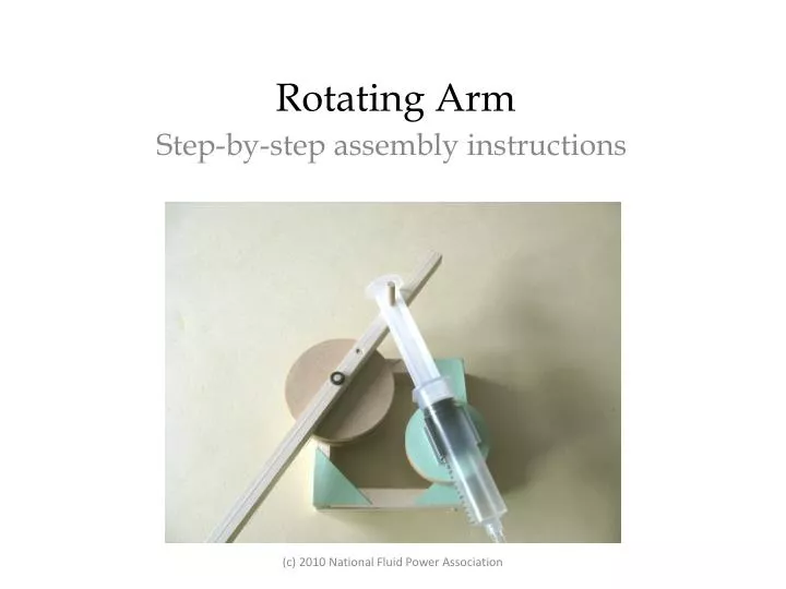
Rotating Arm. Step-by-step assembly instructions. Contents of Workshop Rotating Arm Kit. Wooden pieces (⅜” cross-section): 8 X 3⅝”; 1 X 10”(drilled) Green corner gussets: 1 card Syringes, 20cc: 2 (1 has a hole in the plunger) Plastic Tubing: 1 length

E N D
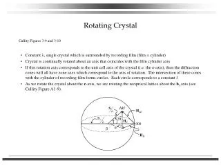
Rotating Arm Step-by-step assembly instructions (c) 2010 National Fluid Power Association
Contents of Workshop Rotating Arm Kit Wooden pieces (⅜” cross-section): 8 X 3⅝”; 1 X 10”(drilled) Green corner gussets: 1 card Syringes, 20cc: 2 (1 has a hole in the plunger) Plastic Tubing: 1 length Wooden dowel, 3/16” diam.: 1 X 2”; 2 X 1½”; 1 X ⅝” Large wheels: 2 (1 drilled) Medium wheels: 2 Axle Holders: 7 Syringe Holder: 1 Mini-washers: 3 Stirring Sticks: 1 Plus a small piece of sandpaper (c) 2010 National Fluid Power Association
Using the 4 X 8” pieces, cut 8 pieces 3⅝” long.Make two 4” squaresusing four 3⅝” pieces for each square. To join pieces of wood together use a green triangle and a small amount of wood glue. Use four corner triangles or gussets on each side of each square. (c) 2010 National Fluid Power Association
On one of the squares glue four axle holders. Two of these are placed so that their smallest angles touch the same corner of the upper side. One is placed in the lower corner and the last is placed so a line through the center of its hole is 1 ½” from the corner opposite the two axle holders. (c) 2010 National Fluid Power Association
Glue the second frame on top of the first and then glue three more axle holders on the top surface. Two of these will be directly above the two on the lower square and the third above the one placed 1 ½” from the corner of the lower square. Use axles to ensure that the holes are directly above and that they turn freely when through both holes. (c) 2010 National Fluid Power Association
Place a 2” axle through a large wheel and glue the wheel to the corner so that it rest on the two axle holders. Before the glue dries ensure that the axle, placed in the lower of the two axle holders glued to the same corner, is vertical. (c) 2010 National Fluid Power Association
Glue in place the ⅝” axle through the offset hole in the other large wheel and the middle of the hole in the 10” piece or arm. Align the center hole of the wheel with the center hole of the arm before the glue dries. (c) 2010 National Fluid Power Association
Glue the two smaller wheels together. Insert a 1 ½” axle through the holes so that it stands proud on one side and is flushed with the other. (c) 2010 National Fluid Power Association
Place the smaller wheels onto a piece of cardboard and cut out its circular shape. (c) 2010 National Fluid Power Association
Glue the shape to the smaller wheels on the flat side. Remove the backing from the syringe holder and press it firmly in place in the center of the card. (c) 2010 National Fluid Power Association
Mount the small wheels and axle on the frame through the two available axle holders and secure the axle underneath using a mini-washer. (c) 2010 National Fluid Power Association
Glue a 1 ½” axle to the available hole in the 10” arm. Ensure that the axle stands proud on the side that does not have the wheel attached to it. (c) 2010 National Fluid Power Association
Assemble the mechanism by mounting the arm onto the large wheels. Ensure that the arm structure rotates freely. Place a mini-washer on the center axle protruding through the arm. (c) 2010 National Fluid Power Association
Identify the syringe that has a hole in its plunger. Mount this plunger onto the axle on the arm. The plunger should rotate through 80˚. (c) 2010 National Fluid Power Association
Place the syringe barrel carefully into the clip so that its lip butts up to the edge of the small wheels. Push the plunger into the barrel, over the safety ridge and stop there. (c) 2010 National Fluid Power Association
Attach the tubing to the syringe and the other syringe to the other end of the tubing. This syringe should be fully closed before it is attached. When it is opened the plunger is pulled into the barrel. (c) 2010 National Fluid Power Association
Operate the acting syringe by pushing and pulling the plunger in and out. As the acting syringe is attached to the arm, the arm will rotate around its center. (c) 2010 National Fluid Power Association