Download

1 / 25
280 likes | 511 Vues
Universal Serial Bus. Grant Heileman. The History of USB. In 1994 a collaborative effort to design a standard for peripheral devices was made between Compaq, DEC, IBM, Intel, Microsoft, NEC, and Nortel. USB 1.0.

E N D
Universal Serial Bus Grant Heileman
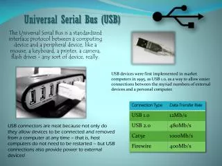
The History of USB In 1994 a collaborative effort to design a standard for peripheral devices was made between Compaq, DEC, IBM, Intel, Microsoft, NEC, and Nortel.
USB 1.0 USB 1.0 was released January 1996. It has a data transfer rate of 12 Mbit/s. However USB did not become popular until its first revision, in 1998. This revision featured the ability to use either 12 Mbit/s(FS) or 1.5 Mbit/s(LS) depending on the device being used.
USB 2.0 April 2000, the specifications for USB 2.0 are released. With a data transfer rate of 480 Mbit/s(HS) this revision was much more superior than its predecessors. However, just because this speed is manageable does not mean that it is often met.
USB cables Signals are sent across USB cables by a twisted set of differential pair wires D+ and D- ( labeled W and G in the picture). USB uses Non Return to Zero Invert (NRZI) data encoding. This means that a 1 will be produced when there is no change in the level of the signal and a 0 will be produced whenever the signal changes. Power is supplied to the devices by the Vbus (+5v) and GND (-5v) wires.
Terms you should know • Slave - A peripheral USB device, could be anything from an Ipod to a vacuum cleaner. A compound device is a slave that contains several sub-devices, referred to as device functions, incased within it. • Hub - A hub is a device that contains multiple ports. Their will always be a root hub. This is the hub that contains the ports connected to the host. After this condition has been meet you may have a device with the sole purpose of giving access to more ports. • Host - Initiates all transactions and bandwidth usage. A host is usually thought of as a computer; however a host can be any device that manages data transactions to and from slaves. The host controls most of the protocol complexity allowing for cheaper slave devices to be produced.
Host Controller A host controller is an additional piece of hardware that is used to guarantee that the data transmitted over the bus is within the USB specifications and no errors have occurred. Along with data processing and error management the HC is used to generate Start of Frame (SOF) packets every 1msec.
Serial Interface Engine The SIE is used in both the host and slave. The SIE is used in the serialization of USB transmissions. USB implements bit stuffing. This means that after six consecutive ones a zero is inserted. The SIE is responsible for bit stuff encoding/decoding the NRZI stream. It also generates the CRCs and confirms any incoming CRC, as well as detects PID, SOP, EOP, reset signals, and resume signals.
Enumeration Once you plug your device in a process called enumeration starts. The host initiates enumeration by… - Sending a reset signal to the device, as well as determine it’s speed - reading the device’s information - assigning a unique 7 bit address to the device - If the device is compatible with the host the device’s drivers are loaded and it is set to a configurable state.
Endpoints An interface is a group of endpoint. A endpoint is the physical structure, located on a USB device, that is the destination of the Packets. Managing interfaces allows the use to send information from the hosts buffers to specific endpoints on the interface. Endpoints can be Out (host to device) or In (device to host)
Endpoint types • Control transfers: used for short, simple commands to the device, and status response to the host. Used by the bus control pipe number 0. • Isochronous transfers: guarantees a set data rate with possible data loss. It is usually the fastest data rate possible. (e.g. realtime audio or video). • Interrupt transfers : devices that need guaranteed quick responses (bounded latency) (e.g. pointing devices and keyboards). • Bulk transfers: large sporadic transfers using all remaining available bandwidth, but with no guarantees on bandwidth or latency (e.g. file transfers).
Pipes A pipe is a logical connection between the appropriate software in the host and a particular endpoint on the device. There are two types of pipes, stream and message. A stream pipe is uni-directional and utilizes the isochronous, interrupt, and bulk data transfers. A message pipe is bi-directional and is exclusively used for control data transfers. Endpoint Zero is usually reserved for message pipes.
Packet Fields USB data is transmitted LSB first and contains packages consisting of these fields.
Sync • This is a mandatory field that synchronizes the slave’s clock with the host’s clock. This field is 8 bits long in low and full speed devices and 32 bits long in high speed devices. The last two bits identify the start of the PID field.
PID • A “Packet ID” is a 8 bit field used to identify which type of packet is being sent. Only 4 bits are needed for this but to guarantee accuracy these 4 bits are complemented and repeated.
ADDR • This is a 7 bit field used to distinguish between slave device. The all 0’s address is used for devices that have not been assigned an address yet. This allows for a maximum of 127 devices to be connected.
ENDP • The endpoint field contains 4 bits, this allows for a total of 16 endpoints. However low speed devices may only have 4 endpoint, this includes the default pipes.
CRC • The Cyclic redundancy check is a field used to check for transmission errors in the token and data packets of any non-PID transaction.
EOP • The End of packet field consists of a Single Ended Zero (SE0, D+ and D- are low) for two bit times followed by a J (differential 1 for full-speed devices and 0 for low-speed devices) for 1 bit time. This field is used so the slave can identify when a packet ends and a new sync can start.
Packet Types USB uses four different packet types. Token, Data, Handshake, and start of frame.
Token Packets Token packets are used to identify the type of transaction that will be taking place. • In – Tells the slave that the host needs to read information. • Out – Tells the slave that the host needs to send information • SOF – Indicates the start of frame. • Setup – Tells the slave a control transaction is starting Token packets must be formatted like this Sync PID ADDR ENDP CRC5 EOP
Data Packets Data packets contain the payload, low speed devices can have a maximum size of 8 bytes while full and high speed devices can have a maximum size of 1023 bytes and 1024 bytes respectively. The data must be sent in multiples of bytes. Data0 and Data1 can transmit up to 1024 bytes of data. High speed devices have an additional two packet types, Data2 and Mdata. Data packets must be formatted like this Sync PID DATA CRC16 EOP
Handshake packets Handshake packets are used to determine whether or not the the transmission of the data packet was successful. The types of handshake packets consist of. • ACK – Acknowledges the packet was received. • NAK – Informs the host that the device momentarily can not send or receive data. • STALL – The device is in a state that requires intervention form the host. Either the endpoint is frozen or the Setup is not supported. Handshake packets must be formatted like this. Sync PID EOP
Start of frame Packets • The SOF packet is sent by the host every 1msec (FS bus) or 125usec (HS bus). The frame number is 11 bytes long. Sync PID Frame Number CRC5 EOP