Download
1 / 28
341 likes | 1.03k Vues
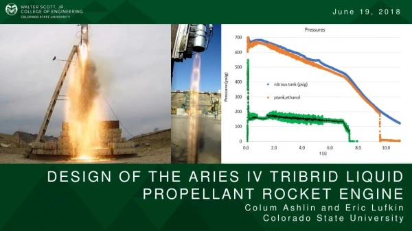
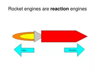
Bi-propellant Liquid Rocket Engines. Ox. P c. Fuel. Pressurant ~5000psi. ~700psi. ~500psi. Pressure-Fed vs. Pump-fed Systems. Liquid Rocket Engines fall into two major categories depending on how propellants are supplied to the engine.

E N D
Ox Pc Fuel Pressurant ~5000psi ~700psi ~500psi Pressure-Fed vs. Pump-fed Systems Liquid Rocket Engines fall into two major categories depending on how propellants are supplied to the engine. A separate, high pressure inert gas (N2 or He) is used to provide the liquid to the combustion chamber. - creates a simpler engine, lower cost - high pressure tanks and lines add system weight - lower Pc = lower Isp As a general rule, pressure-fed systems are not competitive with pump-fed systems for large scale engines. Pressure-fed Psource Ptank Pcombustor Pressure Time ON OFF
Pc Pump-fed Systems Ox ~30psi Fuel ~1000 - 3000 psi Turbo pump - higher Pc , so higher Isp - lower tank pressure and weights - more complexity and cost From this point forward, we will concentrate on pump-fed engines. How do we drive the turbines for the turbopumps?
Engine Cycles Open (drive gases do not go through throat) Gas Generator- some propellant is diverted into a smaller chamber to generate drive gases.ExampleF-1J-2 Tap-off cycle- some gas is bled directly from the combustion chamber to drive turbines.ExampleJ2-S As a general rule, open cycles are slightly lower performance (2%-5% lower Isp) than closed cycles.
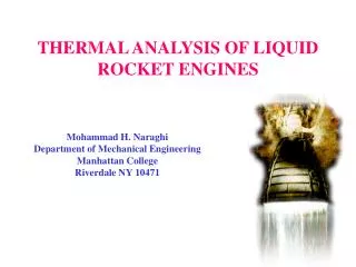
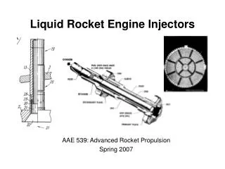
Top, liquid-fuel rocket engine showing location of injector. Bottom, representative types of injector. (Cornelisse et al., p. 209; Sutton, p. 208) http://history.nasa.gov/SP-4221/p19.htm
Open Cycle – Turbine exhaust is discharged into engine nozzle or out separate nozzle Closed Cycle – Turbine exhaust is injected into combustion chamber - Higher Isp (1-5%) because turbine exhaust goes through full pressure ratio of engine - Pump turbine must operate at a higher pressure than an open cycle turbo-pump Open or Closed Cycle Feed Mechanisms Courtesy Dr. Dianne Deturris, CalPoly U.
Open and Closed Cycle Feed Mechanism Layouts Courtesy Dr. Dianne Deturris, CalPoly U.
Closed Cycle – drive gas propellants also go through throat (no waste of propellants) Expander cycle- fuel is vaporized in cooling jackets and used to drive the turbines. Example: Pratt & Whitney RL-10 rocket engine, the first to use liquid hydrogen. Thrust, 67 kN at altitude; exhaust velocity, 4245 m/s; exit, diameter, about 1 m. First engine run. July 1959, two of these engines powered the Centaur stage. http://www.hq.nasa.gov/office/pao/History/SP-4404/ch10-7.htm
F-1 Engine Large combustion chamber and bell -injector plate at the top - RP-1 and LOX injected at high pressure. LOX dome above injector also transmits the thrust from the engine to the rocket's structure. Single-shaft turbopump mounted beside combustion chamber. Turbine at bottom, driven by exhaust gas from fuel-rich gas generator. Turbine exhaust passes through heat exchanger, to wrap-around exhaust manifold and into nozzle periphery - to cool and protect the nozzle extension from the far hotter core flow. Fuel pump above turbine, on the same shaft. Two inlets from fuel tank and two valved outlets to injector plate and gas generator. Fuel & RJ-1 ramjet fuel also used as lubricant and hydraulic working fluid. LOX pump at top of turbopump shaft with single, large inlet in-line with the turboshaft axis. Two outlet lines with valves feed the injector plate and gas generator.Interior lining of combustion chamber and engine bell – fuel feed pipework. Igniter with cartridge of hypergolic triethylboron with 10-15% triethylaluminium, with burst diaphragms at either end, in high pressure fuel circuit, with its own inject point in the combustion chamber. history.nasa.gov/ap08fj/ 01launch_ascent.htm
S-II stage: 5 uprated J-2s: LH2- LOX 5,087 kN. Designed for restarting in flight but implemented in the S-IVB J-2 history.nasa.gov/ap08fj/ 01launch_ascent.htm
Staged-CombustionA pre-burner is used to vaporize all of the fuel – the residual fuel-rich gas drives the turbine and then is directed to the main chamberExample: SSME (LOX/LH2) http://faculty.erau.edu/ericksol/courses/ms603/spaceflight.html
Sample Engine Balances Courtesy Dr. Dianne Deturris, CalPoly U. & Boeing Co., Rocketdyne Division
FUEL OXID Fuel Turbopump Oxid Turbopump P = 300 T = 40 w = 207.4 P = 300 T = 168 w = 1244.5 5300 1325 82.6 5300 1325 198.5 3150 1190 198.5 3150 1230 82.6 6460 91 207.4 4410 180 1128.7 8100 200 115.7 DP = 30 DP = 30 6260 92 116.8 6260 92 48.6 Line DP = 50 Line DP = 30 7580 200 81.7 7580 200 34.0 Line DP = 20 FPBOV DP = 500 OPBOV DP = 500 Line DP = 50 MFV DP = 100 Line DP = 50 Line DP = 110 6310 92 207.4 8080 200 115.7 3120 1000 41.5 4000 180 1128.7 4300 180 1128.7 MOV DP = 300 5250 400 41.5 Line DP = 50 Orifice DP = 1730 Line DP = 50 6260 92 41.5 S.L. Thrust (lbf) = 550,000 Vacuum Thrust (lbf) = 656,000 S.L. Isp (sec) = 379 Vacuum Isp (sec) = 452 Main Pc (psia) = 2,800 P = Press, psia T = Temp, deg-R w = Flow, lb/sec DP = Pressure drop, psid FPBOV = Fuel preburner oxid valve OPBOV = Oxid preburner oxid valve MFV = Main fuel valve MOV = Main oxidizer valve 5200 400 41.5 Line DP = 50 4900 980 41.5 Sample Staged-Comb. Cycle Engine Balance Courtesy Dr. Dianne Deturris, CalPoly U. & Boeing Co., Rocketdyne Division
OXID FUEL Fuel Turbopump Oxid Turbopump 2180 400 98.7 P = 300 T = 40 w = 109.7 P = 300 T = 168 w = 658.0 DP = 20 1840 380 88.8 6175 92 109.7 2200 400 98.7 2380 177 658.0 OTBV w = 9.9 (10%) 5470 470 109.7 1840 395 109.7 TBV w = 11.0 (10%) Line DP = 75 Line DP = 80 DP = 20 Line DP = 30 2100 177 658.0 MOV DP = 200 5500 620 43.9 MFV DP = 100 6000 94 43.9 S.L. Thrust (lbf) = 239,000 Vacuum Thrust (lbf) = 350,000 S.L. Isp (sec) = 312 Vacuum Isp (sec) = 456 Main Pc (psia) = 1,600 6000 94 109.7 P = Press, psia T = Temp, deg-R w = Flow, lb/sec DP = Pressure drop. psid CCV = Coolant control valve MFV = Main fuel valve MOV = Main oxid valve OTBV = Oxid turbine bypass valve TBV = Turbine bypass valve 5500 430 54.9 CCV w = 10.9 5670 97 54.9 DP = 330 Sample Full Expander Cycle Engine Balance Courtesy Dr. Dianne Deturris, CalPoly U. & Boeing Co., Rocketdyne Division
FUEL OXID Fuel & Oxid Turbopump 300 2100 1.7 P = 50.0 T = 530 w = 41.0 P = 50.0 T = 530 w = 20.0 2140 550 20.0 1400 540 41.0 17 1700 1.7 Orifice DP = 400 Orifice DP = 840 1000 540 0.2 Line DP = 100 1200 550 1.5 Line DP = 100 GGFV DP=100 GGOV DP = 60 Orififice DP = 300 Line DP = 10 Line DP = 2 Line DP = 50 1100 820 18.5 1300 540 40.8 MOV DP = 50 15 1702 1.7 2130 550 18.5 Overboard Dump MFV DP = 30 Orifice DP = 200 P = Press, psia T = Temp, deg-R w = Flow, lb/sec DP = Pressure Drop psid GGFV = Gas-generator fuel valve GGOV = Gas-generator oxid valve MFV = Main fuel valve MOV = Main oxid valve Vacuum Thrust (lbf) = 20,000 Vacuum Isp (sec) = 328 Main Pc (psia) = 800 2100 550 18.5 1900 550 18.5 Sample Gas Generator Cycle Engine Balance Courtesy Dr. Dianne Deturris, CalPoly U. & Boeing Co., Rocketdyne Division
“The Space Shuttle Main Engine (SSME) has 4 turbopumps, 2 low-pressure and 2 high-pressure, each pair is used to force liquid hydrogen and oxygen into the main combustion chamber, where propellants are mixed and burned. With the help of a nozzle, which is regeneratively cooled using liquid hydrogen, thrust is produced after the hot gases are expanded and accelerated. Each high-pressure pump has a preburner, where all the fuel and some oxygen are burned, the gases produced are used to run two-staged turbines that move the pumps' impellers.” http://web.mit.edu/plozano/www/picts/ssme.gif
In general, closed cycles like staged-combustion or expander will have higher Isp than GG or tap-off (open cycles). However, cost, pressure and complexity are all more. Examples: RD-180 / Atlas III SSME .
Example LOX/RP GG Engine Mixture Ratio Main Chamber Gas Generator (much lower – better to drive turbine) Overall or “tanked” The net Isp must be calculated from the main and GG mass flows.
Isp (main chamber) (at sea-level) ISP (Gas Generator) (at sea-level) As a result, the overall Isp is less than just the nozzle portion.
Overall Isp Isp (net at sea-level) (staged combustion doesn’t have this effect)
Predicting Engine Pressures For a typical engine, the system pressures are much higher than the chamber pressure, Pc. Humble gives some rules of thumb for determining pressures. Open Cycles (like GG) Depending on line diameter & length if regenerative cooled in fuel side. Injector losses Injector losses for throttled engine
Example For the LH2 side of a Pc = 100 atm GG engine (unthrottled, regen cooled) Assume the tank pressure is 3 atm, and V=10m/s. (depends on vehicle acceleration and tank height) When this falls too low, we need a boost pump. (within the range of a 1 stage pump for LH2.)
The pressure “head”, H is The same calculation can be performed on the LOX side of this cycle. Note: Here the turbine is outside the main thrust chamber- the GG operates at a lower pressure. The object of the turbine is to extract this energy from the flow.
Closed-Cycle Engine For a closed-cycle like staged-combustion or expander, we cannot tolerate this type of pressure loss in the turbine because it is in series with the chamber. The fuel from the fuel pump goes through the nozzle cooling tubes, gets vaporized. Most of it enters the injector and then the combustion chamber. The rest enters the preburner where it mixes with part of the oxidizer and reacts. The exhaust then drives the two turbines before entering the combustor. For this turbine arrangement (series) For a closed cycle, we’d like to have (otherwise pressures are too high in pump) So, for the fuel side and
SSME Pressure Analysis Example Pc ~ 206 atm. Throttleable, staged combustion with regenerative cooling. Fuel side: Assuming injector drop of 0.3 Pc Use Then pressure at turbine inlet = 402atm. Assume that the pump inlet pressure = 3atm
The corresponding pressure “head”, H is This magnitude of pressure head requires a 2- or 3-stage pump. Power Balance In order to drive the pumps, we must extract work from the turbines. watts Note: 1 HP = 550 ft-lb/s = 745.7Watts