Download

1 / 45
460 likes | 704 Vues
EFFECT OF MATERIAL PROPERTIES ON DESIGN. Dr. Zuhailawati Hussain EBB 224 Rekabentuk bahan Kejuruteraan. 1. Factors affecting the behaviour of materials in components. Design should take into account function, material properties & the manufacturing processes. , Fig 6.1

E N D
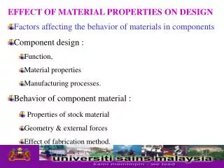
EFFECT OF MATERIAL PROPERTIES ON DESIGN Dr. Zuhailawati Hussain EBB 224 Rekabentuk bahan Kejuruteraan
1. Factors affecting the behaviour of materials in components • Design should take into account function, material properties & the manufacturing processes. , Fig 6.1 • Secondary relationships: material properties-manufacturing processes, function-manufacturing processes, and function-material properties • Behavior of component material depends on influence of properties of stock material, geometry & external forces, & effect of fabrication method, Fig. 6.2. • Fig 6.2 also shows secondary relationship.
FUNCTION & CONSUMER REQUIREMENTS COMPONENT DESIGN MANUFACTURING PROCESSES MATERIAL PROPERTIES Fig 6.1 Factors should be considered in component design
PROPERTIES OF STOCK MATERIAL BEHAVIOR OF MATERIAL IN THE COMPONENT GEOMETRY & EXTERNAL FORCES EFFECT OF FABRICATION METHOD Fig 6.2 Factors should be considered in anticipating the behavior of material in the component
2. Statistical variation of material properties • In practice, material properties are seldom homogenous or isotropic, as they are sensitive to variations in parameter such as : • Composition, heat treatment & processing condition. • Others that influence material behavior • Surface roughness, internal stress, sharp corners and stress raiser. • Variation in material properties can be solved by choosing factor of safety. Factor of safety accommodates unknown influences that affect the life of component under service condition.
2.1 Statistical Parameter • Material properties can be statistically described by mean value (x), standard deviation () and coefficient of variation (). • x1, x2, x3 = values of different measurements of the same material property, n= number of measurement
v = /x (eq. 3) • Coefficient variation (dimensionless quantity) is useful in assessing the relative variability from different source. • Smaller values of standard deviation & coefficient of variation indicate more homogenous material
2.2 Normal distribution of properties • Frequently, all material properties are normally • distributed. • From the normal distribution, confidence limits can be • determined • The probabilities of obtaining values at plus or minus • 1,2 or 3 standard deviation from the mean value are • 68.26%, 95.46% & 99.73% respectively, Fig. C.6 • Probability that a value would occur outside the range • represented by plus or minus two std deviation from the • mean is 4.54%, or the confidence level that the value • will be found within the limits is 95.46%.
Assuming an experimental data ( no. of sample > 100) is following a normal distribution, the standard deviation is approximated as • = (max value of property – min value)/6 (eq.4)
Example 1 • If the range of strength of an alloy is given as 800 – 1200 MPa, and the mean value can be taken as 1000 MPa • Solution • The mean strength can be taken as 1000 MPa • The standard deviation can be estimate as • = ( 1200 – 800 )/6 = 66.67 MPa • The coefficient of variation v is then • v = 66.67/1000 = 0.0667
If results are obtained from a sample of • 25 test, eq. 4 is divided by 4 • 5 test, eq. 4 is divided by 2
3. Effect of component geometry • In almost engineering components and machine have to incorporate design features which introduce changes in their cross-section. • E.g. oil holes, bolt heads, gear teeth • Changes in cross section causes localized stress concentration
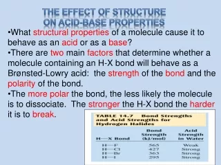
3.1 Stress Concentration Factor • Severity of stress concentration depends on the geometry of the discontinuity and nature of the material. • Stress concentration factor, Kt = Smax/Sav • Smax= maximum stress at discontinuity and • Sav,= nominal stress. • Kt, value depends only on geometry of the part. • Under static load, Kt gives an upper limit to the stress concentration value & applies only to brittle & notch sensitive materials. • Should considered when using high-strength, low ductility, case-hardened & / or heavily cold work materials.
3.2 Stress concentration in fatigue. • Stress concentration also should be considered in components that are subject to fatigue loading • Kf, fatigue stress concentration factor, • Kf = endurance limit of notch free • endurance limit of notched part • Notch sensitivity factor, q = Kf – 1 (eq 8.8) • Kt – 1 • q varies from 0 to 1, as appproach to 1 the material becomes sensitive to the presence of notches • q also depends on component size, increases as size increase
Kf = Kt, the value of q=1 & materials becomes sensitive to notches • Kf = 1, q = 0, material is not sensitive to notches • In making a design, • Kt is usually determined from the geometry of part • q can be specified when the material is selected • Eq 8.8 is solved for Kf • also depend on component size thus stress-raiser are dangerous in larger masses.
3.3 Guidelines for design. • Stress concentration can be a source of failure in many cases, esp. when designing with high strength materials & under fatigue loading. • The following design guidelines should be observed if the effect of stress concentration are to be kept to a minimum: • 1. Abrupt changes in cross-section should be avoided. • Fillet radii or stress-relieving groove should be provided. • Fig. 11.3(a) • 2. Slot and grooves should be provided with generous run-out radii and with fillet radii in all corners. • Fig. 11.3(b)
3. Stress relieving grooves or undercut should be • provided at the end of threads and splines. • Fig. 11.3(c) • 4. Sharp internal corners and external edges should be avoided • 5. Oil holes & similar features should be chamfered and the bore should be smooth • 6. Weakening features like bolt and oil holes, identification marks, and part number should not be located in highly stressed areas. • 7. Weakening features should be staggered to avoid the addition of their stress concentration effects. • Fig. 11.3(d)
4. Design aspect-loading condition • Static loading – load is applied gradually and remains applied throughout part’s life. • Repeated loading – applied and removed several times (repetitive) during life. Fail by fatigue at stress lower than yield strength. Higher design factor is needed. • Impact – require large design factor. (i) sudden load causes stresses much higher than computed. (ii) require part to absorb energy of the impact. • Static loading but at high T – consider creep, microstructural changes, oxidation & corrosion & influence of method of fabrication on creep.
4.1 Designing For Static Strength • Design based on the Static strength • Ability to resist short-term steady load at moderate T. • Measured in terms as yield strength, UTS, compressive strength & hardness. • Aimed at avoiding yielding of the component in the case of soft, ductile materials and at avoiding fracture in the case of strong, low toughness materials. • Component must be strong enough to support the service load & may require enough stiffness to ensure deflections do not exceed certain limits. • Stiffness, important in machine elements to avoid misalignment and maintain dimensional accuracy.
Elasticity (Young’s M) • important when designing struts, columns & thin-walled cylinders subjected to compressive axial loading where failure can take place by buckling.
4.2 Designing for simple axial loading • Component and structure made from ductile material are usually designed, so that no yield take place under static loading condition • But, when the component is subjected to uniaxial stress, yielding take place • When local stress reaches the yield strength of the material • Critical cross-sectional area, A ; • A = KtnsL • YS • Kt = stress concentration factor, L = applied load • ns = factor of safety, YS = yield strength
In some cases the stiffness of the component, rather than its strength, is the limiting factor. • In such cases, limits are set on the extension in the component. See example. • Example: It is required to select a structural material for the manufacture of the tie rods of suspension bridge. A representative rod is 10 m long & should carry a tensile load of 50 kN without yielding. The max. extension should not exceed 18 mm. Which one of the materials listed in Table 2.7 will give the lightest load ?
Calculations of the area will be carried out twice: • 1. Area based on yield strength = load • YS • 2. Area based on deflection = load x length • E x deflection • The larger of the two areas will be taken as the design area & will be used to calculate the mass.
Area based on yield strength = • Area based on deflection = • Mass = • The results show that steel A717 grade 70 & maraging steel grade 200 give the least mass. • The former steel is more ductile & less expensive it will be selected.
4.2.1 Factor of safety, ns. • Is applied in designing component to ensure it will satisfactory perform its intended function • To get the strength of material at allowable stress. • The definition, strength of material depends on the type of material and loading condition. E.g. UTS-brittle, YS-ductile • The factor of safety, ns. • ns = S / Sa • S = Nominal strength, Sa = Allowable strength / Design strength • It is important to define which type of service condition will the material work on before calculating the ns. • Normal working condition • Limit working condition, such as overloading
Brittle material such as gray cast iron do not exhibit yielding, so design based on ultimate strength. • General - % of elongation in a 2-in gage length is less than 5% • Brittle. e.g Al – except for castings, all is ductile. • Ductile material – large plastic deformation, so unfit for intended use. Design based on yield strength. • Design stress guidelines : • Ductile material, δd = Sy / 2 • Brittle material, δd = UTS / 6
4.2.2 Determine Dimensions & Shape of Component • Given – (1) Magnitude & type of loading & (2) material condition. • Determine yield & ultimate strength & % elongation of material. Decide ductile or brittle. • Specify design factor (factor of safety). • Compute design stress. • Write equation for expected max stress. For direct normal stress, δmax = F/A • Set δmax = δd & solve for required cross-sectional area. • Determine minimum required dimension.
Contoh Soalan : Satu struktur penyokong mesin akan dibebankan dengan beban tegangan statik 16kN. Dicadangkan, dihasilkan dalam bentuk rod empat segi daripada keluli gelek panas, AISI 1020. Berikan dimensi yang sesuai untuk keratan rentas rod tersebut. Analisis : Objektif – tentu dimensi keratan rentas rod. Diberi – F = 16 kN = 16 000 N beban statik. Bahan – AISI 1020 HR, Sy = 331 MPa, 36% elongation
Jawapan : Analisis – Biar δ = δd = Sy / 2 bahan mulur. Analisis tegasan – δ = F/A, maka A diperlukan A = F / δd Tetapi A = a2 (a = dimensi sisi square) Dimensi minimum yang dibenarkan a = A Maka Tegasan, δd = Sy/2 = 331 MPa/2 = 165.5 MPa (N/mm2) Keratan rentas, A = F/ δd = (16 000 N) = 96.7mm2 (165.5 N/mm2) Dimensi minimum a = A = 96.7 mm2 = 9.83 mm. Dimensi minimum a = 10 mm.
4.3 Designing for Torsional Loading • Torsional – loading of a component / part that tends to cause it to rotate or twist. • When torque is applied, shearing stress is developed & torsional deformation occurs, resulting in an angle of twist of one end of part relative to the other. • Material must have sufficient rigidity for the part to perform properly in service. • Torque = T = F x d • where F = applied force & d = distance from action of • force to axis of the part. • Power = torque x rotational speed (n in rad/s).
Torsional shear stress, ζmax = Td / 2Ip • where T = applied torque, d = diameter & Ip = polar moment of inertia of the cross section. • Critical cross sectional area of a circular shaft can be calculated, 2Ip = KtnsT • d ζmax • where Kt = stress concentration factor, ζmax=Torsional • shear stress, ns = factor of safety, • Ip = polar moment of inertia of the cross section, • T = Torque
Ip = πd4 / 32 for solid circular shaft • Ip = π(d04 – di4) / 32 for hollow circular shaft of inner di & outer d0. • ASTME code of practice ; allowable value of shear stress of 0.3 yield or 0.18 UTS, which is smaller. • For ductile material, design shear stress = yield / 2N (steady torsion, N = 2, so ζd = yield / 4)
Torsional rigidity of component is usually measured by the angle of twist, θ, per unit length. For circular shaft, θ is given by, • θ = T / GIp • where G = modulus of elasticity in shear • = E / (2(1 + ν)) • where ν = Poisson’s ratio. • Usual practice is to limit the angular deflection in shafts to about 1 degree, i.e π/180 rad, in length of 20 times the diameter.
4.4. Designing for Bending • Beam – component that carries load transversely, that is, perpendicular to its long axis. • Loading – normal concentrated load, inclined concentrated load, uniformly distributed load, varying distributed load & concentrated moments. • Moment – an action that tends to cause rotation of an object. Can be produced by a pair of parallel forces acting in opposite directions, called couple. • Beam types ; simple, overhanging, cantilever, compound & continuous. • Bending moments – internal moments cause bending.
Load M Cantilever – one fixed end, provide support & moment produced by load Overhanging – bend downward, negative bending
F F Compound – two or more parts extending in different directions. Continuous – extra support or both ends fixed, require different approaches to analyze forces & moments.
Relation between bending moment, max allowable stress & dimensions given by ; • Z = nsM • YS • where Z = section modulus = I/c • c = distance from center of gravity of cross section to the outermost fiber/beam. • I = moment of inertia of cross section with respect to neutral axis normal to direction of load. • M = bending moment & YS = max allowable stress. • ns = factor of safety.
When load is placed on a beam, the beam is bent and every portion of it is moved in a direction parallel to the direction of the load. • The distance that a point on the beam moves/ deflection depends • Its position in the beam • Type of beam • Type of support
Example Question : Determine the diameter of a cantilever beam of length 1 m and rectangular cross section of depth-to-width ratio 2:1. The cantilever is expected not to deflect more than 50 mm for every 1000 N increment of load at its tip. The material used in making the beam is steel AISI 4340 with a yield strength of 1420 MPa and UTS 1800 MPa. What is the max permissible load ? Assume a suitable factor of safety.
Example Solution : The deflection ( y ) of a cantilever beam under a load L acting on its tip is given by relationship : y = ( Ll3 ) / ( 3 EI ) where l = the length of cantilever E = elastic modulus of the cantilever material = 210 Gpa I = the second moment of area of the cross-section From fig 4.3 I = b x ( 2b )3 = 1000 x 1 x 1000 12 50 x 3 x 210 x 109 Where b is the width of the beam; b = 14.77 mm
Example Taking a factor of safety n = 1.5 and using eq. Z= I/c, c=H/2=b Z = 2148 mm3 = ( nM ) / YS = ( 1.5 x L x l ) / 1420 The safe value of L = 2033 N