Download
1 / 43
440 likes | 712 Vues
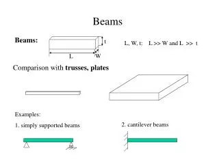
MOEMS with guided wave beams Paul V.Lambeck Lightwave Devices Group MESA + Institute University of Twente Enschede, The Netherlands. Outline 1.Introduction 2. MOEMS free space beams 3. MOEMS guided beams - integrated optics (IO) - IO-MEMS general - IO-MEMS MESA + devices

E N D
MOEMS with guided wave beams Paul V.Lambeck Lightwave Devices Group MESA+ Institute University of Twente Enschede, The Netherlands
Outline • 1.Introduction • 2. MOEMS free space beams • 3. MOEMS guided beams • - integrated optics (IO) • - IO-MEMS general • - IO-MEMS MESA+ devices • 4. Conclusions
transmission translation rotation deformation (absorption) reflection (diffraction) Dependent on - MEMS-structure - light beam properties wavelength,polarization spatial: shape, angle etc
MOEMS actuating MEMS OPTICS sensing // ( activating) // // Chemical domain Bio-reactor, sensor
OPTICAL TELECOMMUNICATION Routing (switching) discrete Adjustment of functions continuous
M.Hoffmann, P.Kopka,T.Gross,E.Voges, JMM vol 9 (1999), pp 151-155
LOSS • Divergent exit beam • reflection
MOEMS FREE SPACE BEAM SWITCH MATRIX in in out out
add in drop out
Industrial interest In MOEMS 95 00 02 year
Set of discrete q values modes Slabtype-waveguide Ray picture ncore>ncladding,nsubstrate
Powerprofile P(x) ~ |E(x)|2 • Speed n=c/Neff (n=c/n) • Wavelength • Number of modes Waveguides – Maxwell theory nclad ncore nbuffer • TE-TM • Propagation speed c/Neff • Power • Power profile
P~E2 E Power profile Field profile Evanescent field
Waveguiding channels Si3N4 200 nm SiO2 3 mm
evanescent field n2 b n1 a ac n1sin a = n2 sin b sin ac = n2/n1 total reflection n1 n < n1 J.E.Fouquet, Agilent, pp 204-206
add in out drop
SiON Technology SiON n= 1.47-2.00 PECVD LP/PE CVD lateral structuring SiON n= 1.48-2.0 SiO2 n= 1.45 Thermal Oxidation Si wafer n= 3.5 Flexible: 1.45 = nSiO2 < nSiON < 2.01 = n Si3N4 Well developed for IO-devices for optical telecommunication K.Worhoff,L. Hilderink,A.Driessen, P.Lambeck, J Electrochem Soc 149,(2002) pp85-91
-1 10 30 -2 20 10 Attenuation dB/cm -3 10 10 -4 0 10 -5 10 0 . 0 0 . 2 0 . 4 0 . 6 0 . 8 1 . 0 Airgap (mm) Si3N4 core, SiO2 buffer, SiO2 MP DN’
ΔNeff required power ~ 10 –3 during switching ~ 10-2 continuously ~ 10-1during switching Electro-optisch Thermo-optisch Mechano-optisch (evanescent field)
Pout/Pin 1 0 0 Neff Switch condition Neff > Neff,c Digital Optical Y-junction switch (DOS)
Disc resonator as add/drop filter Condition for add/drop
GRATING SWITCH Reflection condition: Preflected /Pin wavelength
switch condition objective ~i – ~f Neff > Neff,c i - f analogue
G.J.M.Krijnen, T.S.J.Lammerink,P.V.Lambeck, M.Elwenspoek, J MM vol 9, (1999), pp 203-205
G.J.Veldhuis, T.Nauta, C.Gui, J.W.Berenschot,P.V.Lambeck, J.Sel Top Quant Electr. Vol 5 (1999),pp 60-66
Cross section resultaten
-1 10 1000 -2 10 -3 10 -4 10 100 d=100 nm in air DN’ Attenuation dB/cm -5 10 -6 10 -7 10 10 d=100 nm in air -8 10 -9 10 d=300 nm, SiO2 buffer, extrapolated -10 10 1 0 1 2 3 4 5 6 Airgap (mm) Systems comparison
Sensing Iin Iout m Reference Mach Zehnder Interferometer • perfect symmetry • Loss-less • Perfect symmetry • Loss-less dNeff = 10-8
Fiber-chip coupler Optical Modulator Evanescent field Sensor Fiber-chip coupler 20 nm 5 µm 4 µm 350 nm 80 nm 300 nm 3 µm 1 µm 100 nm Silicon dioxide (Wet Ox.) Silicon nitride Cr/Au electode Silicon dioxide (PECVD) Zinc oxide Silicon MESA+ : M. Dijkstra, G. Altena, P. Lambeck, H. Hoekstra
Conclusions 1.MEMS + free beam optics: useful functions for Optical telecommunication have been shown. 2.MEMS + Integrated Optics: - good prospects for integrated microsystems for optical telecommunication and sensing - challenge to MEMS and Integrated Optics