Download
1 / 25
250 likes | 464 Vues
Computer Structure Power Management Lihu Rappoport and Adi Yoaz Thanks to Efi Rotem for many of the foils . Processor Power Components. The power consumed by a processor consists of Dynamic power: power for toggling transistors and lines from 0 1 or 1 0

E N D
Computer StructurePower ManagementLihu Rappoport and Adi YoazThanks to Efi Rotem for many of the foils
Processor Power Components • The power consumed by a processor consists of • Dynamic power: power for toggling transistors and lines from 01 or 10 • αCV2f : α– activity, C – capacitance, V – voltage, f – frequency • Leakage power: leakage of transistors under voltage • function of: Z – total size of all transistors, V – voltage, t – temperature • Peak power must not exceed the thermal constrains • Power generates heat • Heat must be dissipated to keep transistors within allowed temperature • Peak power determines peak frequency (and thus peak performance) • Also affects form factor, cooling solution cost, and acoustic noise • Average power • Determines battery life (for mobile devices), electricity bill, air-condition bill • Average power = Total Energy / Total time • Including low-activity and idle-time (~90% idle time for client)
Performance per Watt • In small form-factor devices thermal budget limits performance • Old target: get max performance • New target: get max performance at a given power envelope • Performance per Watt • Increasing f also requires increasing V (~linearly) • Dynamic Power = αCV2f = Kf3 X% performance costs ~3X% power • A power efficient feature – better than 1:3 performance: power • Otherwise it is better to just increase frequency (and voltage) • Vmin is the minimal operation voltage • Once at Vmin, reducing frequency no longer reduces voltage • At this point a feature is power efficient only if it is 1:1 performance: power • Active energy efficiency tradeoff • Energyactive = Poweractive × TimeactivePoweractive / Perfactive • Energy efficient feature: 1:1 performance: power
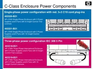
LAN 2% Fan 2% DVD 2% ICH3% Display (panel + inverter) 33% CLK 5% HDD 8% GFX 8% Misc. 8% CPU 10% MCH 9% Power Supply 10% Platform Power • Processor average power is <10% of the platform
Managing Power • Typical CPU usage varies over time • Bursts of high utilization & long idle periods (~90% of time in client) • Optimize power and energy consumption • High power when high performance is needed • Low power at low activity or idle • Enhanced Intel SpeedStep® Technology • Multi voltage/frequency operating points • OS changes frequency to meet performance needs and minimize power • Referred to as processor Performance states = P-States • OS notifies CPU when no tasks are ready for execution • CPU enters sleep state, called C-state • Using MWAIT instruction, with C-state level as an argument • Tradeoff between power and latency • Deeper sleep more power savings longer to wake
P-states • Operation frequencies are called P-states = Performance states • P0 is the highest frequency • P1,2,3… are lower frequencies • Pn is the min Vcc point = Energy efficient point • DVFS = Dynamic Voltage and Frequency Scaling • Power = CV2f ; f = KV Power ~ f3 • Program execution time ~ 1/f • E = P×t E ~ f2 Pnis the most energy efficient point • Going up/down the cubic curve of power • High cost to achieve frequency • large power savings for some small frequency reduction Power P0 P1 P2 Pn Freq
C-States: C0 • C0: CPU active state Active Core Power Local Clocks and Logic Clock Distribution Leakage
C-States: C1 • C0: CPU active state • C1: Halt state: • Stop core pipeline • Stop most core clocks • No instructions are executed • Caches respond to external snoops Active Core Power Clock Distribution Leakage
C-States: C3 • C0: CPU active state • C1: Halt state: • Stop core pipeline • Stop most core clocks • No instructions are executed • Caches respond to external snoops • C3 state: • Stop remaining core clocks • Flush internal core caches Active Core Power Leakage
C-States: C6 • C0: CPU active state • C1: Halt state: • Stop core pipeline • Stop most core clocks • No instructions are executed • Caches respond to external snoops • C3 state: • Stop remaining core clocks • Flush internal core caches • C6 state: • Processor saves architectural state • Turn off power gate, eliminating leakage Active Core Power Leakage Core power goes to ~0
Putting it all together • CPU running at max power and frequency • Periodically enters C1 C0 P0 Power [W] C1 Time
Putting it all together • Going into idle period • Gradually enters deeper C states • Controlled by OS C0 P0 Power [W] C2 C3 C4 C1 Time
Putting it all together • Tracking CPU utilization history • OS identifies low activity • Switches CPU to lower P state C0 P0 C0 P1 Power [W] C2 C3 C4 C1 Time
Putting it all together • CPU enters Idle state again C0 P0 C0 P1 Power [W] C2 C2 C3 C3 C4 C4 C1 Time
Putting it all together • Further lowering the P state • DVD play runs at lowest P state C0 P0 C0 P1 Power [W] C0 P2 C2 C2 C3 C3 C4 C4 C1 Time
Voltage and Frequency Domains VCC Periphery VCC SA • Two Independent Variable Power Planes • CPU cores, ring and LLC • Embedded power gates – each core can be turned off individually • Cache power gating – turn off portions or all cache at deeper sleep states • Graphics processor • Can be varied or turned off when not active • Shared frequency for all IA32 cores and ring • Independent frequency for PG • Fixed Programmable power plane for System Agent • Optimize SA power consumption • System On Chip functionality and PCU logic • Periphery: DDR, PCIe, Display VCC Core (Gated) VCC Core (ungated) VCC Core (Gated) Embedded power gates VCC Core (Gated) VCC Core (Gated) VCC Graphics VCC Periphery
“Turbo” H/W Control OS Visible States OS Control T-state & Throttle Turbo Mode P0 1C • P1 is guaranteed frequency • CPU and GFX simultaneous heavy load at worst case conditions • Actual power has high dynamic range • P0 is max possible frequency – the Turbo frequency • P1-P0 has significant frequency range (GHz) • Single thread or lightly loaded applications • GFX <>CPU balancing • OS treats P0 as any other P-state • Requesting is when it needs more performance • P1 to P0 range is fully H/W controlled • Frequency transitions handled completely in HW • PCU keeps silicon within existing operating limits • Systems designed to same specs, with or without Turbo Mode • Pnis the energy efficient state • Lower than Pn is controlled by Thermal-State P1 frequency Pn LFM
Turbo Mode Power Gating Zero power for inactive cores No Turbo Core 0 Core 1 Core 2 Core 3 Core 0 Core 1 Core 2 Core 3 Workload Lightly Threaded Frequency (F) Frequency (F)
Turbo Mode Turbo Mode Use thermal budget ofinactive core to increasefrequency of active cores Power Gating Zero power for inactive cores No Turbo Core 0 Core 1 Core 2 Core 3 Core 0 Core 1 Workload Lightly Threaded Frequency (F) Frequency (F)
Turbo Mode Turbo Mode Use thermal budget ofinactive core to increasefrequency of active cores Power Gating Zero power for inactive cores No Turbo Core 0 Core 1 Core 2 Core 3 Core 0 Core 1 Workload Lightly Threaded Frequency (F) Frequency (F)
Turbo Mode Turbo Mode Increase frequency within thermal headroom No Turbo Core 0 Core 1 Core 2 Core 3 Core 0 Core 1 Core 2 Core 3 Active cores running workloads < TDP Core 3 Core 1 Core 0 Frequency (F) Frequency (F) Core 2
Turbo Mode Power Gating Zero power for inactive cores Turbo Mode Increase frequency within thermal headroom No Turbo Core 0 Core 1 Core 2 Core 3 Core 2 Workload Lightly ThreadedAnd active cores < TDP Core 0 Frequency (F) Frequency (F) Core 3 Core 1
Thermal Capacitance Classic ModelSteady-State Thermal Resistance Design guide for steady state New ModelSteady-State Thermal ResistanceANDDynamic Thermal Capacitance Classic model response Temperature More realistic response to power changes Temperature Time Time Temperature rises as energy is delivered to thermal solution Thermal solution response is calculated at real-time Foil taken from IDF 2011
Intel® Turbo Boost Technology 2.0 Power After idle periods, the system accumulates “energy budget” and can accommodate high power/performance for a few seconds In Steady State conditions the power stabilizes on TDP P > TDP: Responsiveness C0/P0(Turbo) Turbo Boost 2.0 Sustain power Use accumulated energy budget to enhance user experience “TDP” Sleep or Low power Time Buildup thermal budget during idle periods Foil taken from IDF 2011
Core and Graphic Power Budgeting • Cores and Graphics integrated on the same die with separate voltage/frequency controls; tight HW control • Full package power specifications available for sharing • Power budget can shift between Cores and Graphics Core Power [W] Heavy CPU workload Sandy Bridge Next Gen Turbo for short periods Total package power Sum of max power Realistic concurrentmax power Specification Core Power Applications Heavy Graphics workload Specification Graphics Power Graphics Power [W] Foil taken from IDF 2011