Download
1 / 82
1k likes | 2.06k Vues
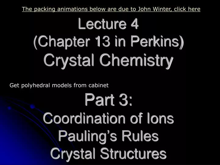
The packing animations below are due to John Winter, click here. Lecture 4 (Chapter 13 in Perkins) Crystal Chemistry Part 3: Coordination of Ions Pauling’s Rules Crystal Structures. Get polyhedral models from cabinet. Coordination of Ions. For ionic bonding, ion geometry ~ spherical

E N D
The packing animations below are due to John Winter, click here Lecture 4 (Chapter 13 in Perkins)Crystal ChemistryPart 3: Coordination of IonsPauling’s RulesCrystal Structures Get polyhedral models from cabinet
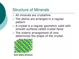
Coordination of Ions • For ionic bonding, ion geometry ~ spherical • Spherical ions will geometrically pack (coordinate) oppositely charged ions around them as tightly as possible while maintaining charge neutrality • For a particular ion, the surrounding coordination ions define the apices (corners) of a polyhedron • The number of surrounding ions is the Coordination Number
+ + + - - - Ionic Compound Formation • Anions – negatively charged • Larger than the un-ionized atom • Cations – positively charged • Smaller than the un-ionized atom • Attraction • Anion – Cation • Repulsion • Anion – Anion • Cation – Cation
Coordination Number and Radius Ratio Radius Ratio is Rc (cation) / Ra (anion) See Figure 13.3 of Perkins See also the Ionic Radii table of Perkins, following the inside front cover from K&D Modified from K&D
Atomic and Ionic Radii Can't absolutely determine: e- cloud is nebulous & based on probability of encountering an e- . In crystalline solids the center-to-center distance = bond length & is accepted to = sum of ionic radii How get ionic radius of X & Y in XY compound??
Atomic and Ionic Radii Pure element first Native Cu. Atomic radius = 1/2 bond length X-ray d100a Ionic radius = a 2 2 a a 4
Atomic Radii • Absolute radius of an atom based on location of the maximum density of outermost electron shell • Effective radius dependent on the charge, type, size, and number of neighboring atoms/ions - in bonds between identical atoms, this is half the interatomic distance - in bonds between different ions, the distance between the ions is controlled by the attractive and repulsive force between the two ions and their charges
Charge and Attractive Force Control on Effective Ionic Radii Approach until Repulsive and Attractive Forces the same
Effect of Coordination Number and Valence on Effective Ionic Radius Higher coordination numbers have larger effective ionic radius Extreme valence shells (1,6,7) have larger effective ionic radius Increasing Ionic radii Decreasing Ionic radii
Coordination Number (CN) (# of nearest neighbors) vs. ionic radius. For cations of one element, higher coordination numbers have larger effective ionic radius
Coordination with O-2 Anions Note: Sulfur can have CN 6 at great depths For example, in the inner core
Coordination Polyhedra • We always consider coordination of anions about a central cation Halite Na Cl Cl Cl Cl
Coordination Polyhedra • Can predict the coordination by considering the radius ratio: RC/RA Cations are generally smaller than anions so begin with maximum ratio = 1.0
Equal sized spheres • “Closest Packed” • Notice:6 nearest neighbors in the plane arranged in a hexagon • Note dimples in which next layer atoms will settle • Two dimple types: • Type 1 upper point NE • Type 2 upper point NW • They are equivalent since you could rotate the whole structure 60o and exchange them Coordination Polyhedra 2 1 Radius Ratio: RC/RA = 1.0 (commonly native elements)
Add next layer (red) • Once first red atom settles in, can only fill other dimples of that type • In this case covered all type 2 dimples, only 1’s are left Closest Packing 1
Third layer ? • Third layer dimples again 2 types • Call layer 1 A sites • Layer 2 = B sites (no matter which choice of dimples is occupied) • Layer 3 can now occupy A-type site (directly above yellow atoms) or C-type site (above voids in both A and B layers) Closest Packing A C
Third layer: • If occupy A-type site the layer ordering becomes A-B-A-B and creates a hexagonalclosest packedstructure(HCP) • Coordination number (nearest or touching neighbors) = 12 • 6 coplanar • 3 above the plane • 3 below the plane Closest Packing
Third layer: • If occupy A-type site the layer ordering becomes A-B-A-B and creates a hexagonalclosest packedstructure(HCP) Closest Packing
Third layer: • If occupy A-type site the layer ordering becomes A-B-A-B and creates a hexagonalclosest packedstructure(HCP) Closest Packing
Third layer: • If occupy A-type site the layer ordering becomes A-B-A-B and creates a hexagonalclosest packedstructure(HCP) Closest Packing
Third layer: • If occupy A-type site the layer ordering becomes A-B-A-B and creates a hexagonalclosest packedstructure(HCP) • Note top layer atoms are directly above bottom layer atoms Closest Packing
Third layer: • Unit cell Closest Packing
Third layer: • Unit cell Closest Packing
Third layer: • Unit cell Closest Packing
Third layer: • View from top shows hexagonal unit cell • (HCP) Closest Packing
Third layer: • View from top shows hexagonal unit cell • (HCP) Closest Packing
Closest Packing • Alternatively we could place the third layer in the C-type site (above voids in both A and B layers) C
Third layer: • If occupy C-type site the layer ordering is A-B-C-A-B-C and creates a cubicclosest packedstructure(CCP) • Blue layer atoms are now in a unique position above voids between atoms in layers A and B Closest Packing
Third layer: • If occupy C-type site the layer ordering is A-B-C-A-B-C and creates a cubicclosest packedstructure(CCP) • Blue layer atoms are now in a unique position above voids between atoms in layers A and B Closest Packing
Third layer: • If occupy C-type site the layer ordering is A-B-C-A-B-C and creates a cubicclosest packedstructure(CCP) • Blue layer atoms are now in a unique position above voids between atoms in layers A and B Closest Packing
Third layer: • If occupy C-type site the layer ordering is A-B-C-A-B-C and creates a cubicclosest packedstructure(CCP) • Blue layer atoms are now in a unique position above voids between atoms in layers A and B Closest Packing
Third layer: • If occupy C-type site the layer ordering is A-B-C-A-B-C and creates a cubicclosest packedstructure(CCP) • Blue layer atoms are now in a unique position above voids between atoms in layers A and B Closest Packing
View from the same side shows the cubic close packing (CCP), also called face-centered cubic (FCC) because of the unit cell that results. Notice that every face of the cube has an atom at every face center. The atoms are slightly shrunken to aid in visualizing the structure Cubic Closest Packing A-layer C-layer B-layer A-layer
Rotating toward a top view Closest Packing
Rotating toward a top view Closest Packing
You are looking at a top yellow layer A with a blue layer C below, then a red layer B and a yellow layer A again at the bottom Closest Packing
What happens when RC/RA decreases? • The center cation becomes too small for the C.N.=12 site (as if a hard-sphere atom model began to rattle in the 12 site) and it drops to the next lower coordination number (next smaller site). • It will do this even if it is slightly too large for the next lower site. • It is as though it is better to fit a slightly large cation into a smaller site than to have one rattle about in a site that is too large.
The next smaller crystal site is the CUBE: Body-Centered Cubic (BCC) with cation (red) in the center of a cube Coordination number is now 8 (corners of cube)
A central cation will remain in 8 coordination with decreasing RC/RA until it again reaches the limiting situation in which all atoms mutually touch. Then a hard-sphere cation would “rattle” in the position, and it would shift to the next lower coordination (next smaller site). What is the RC/RA of that limiting condition?? Set = 1 arbitrary since will deal with ratios Diagonal length then = 2
A central cation will remain in 8 coordination with decreasing RC/RA until it again reaches the limiting situation in which all atoms mutually touch. Then a hard-sphere cation would “rattle” in the position, and it would shift to the next lower coordination (next smaller site). What is the RC/RA of that limiting condition?? Rotate
A central cation will remain in 8 coordination with decreasing RC/RA until it again reaches the limiting situation in which all atoms mutually touch. Then a hard-sphere cation would “rattle” in the position, and it would shift to the next lower coordination (next smaller site). What is the RC/RA of that limiting condition?? Rotate
A central cation will remain in 8 coordination with decreasing RC/RA until it again reaches the limiting situation in which all atoms mutually touch. Then a hard-sphere cation would “rattle” in the position, and it would shift to the next lower coordination (next smaller site). What is the RC/RA of that limiting condition?? Rotate
A central cation will remain in 8 coordination with decreasing RC/RA until it again reaches the limiting situation in which all atoms mutually touch. Then a hard-sphere cation would “rattle” in the position, and it would shift to the next lower coordination (next smaller site). What is the RC/RA of that limiting condition?? Rotate
A central cation will remain in 8 coordination with decreasing RC/RA until it again reaches the limiting situation in which all atoms mutually touch. Then a hard-sphere cation would “rattle” in the position, and it would shift to the next lower coordination (next smaller site). What is the RC/RA of that limiting condition?? Rotate
A central cation will remain in 8 coordination with decreasing RC/RA until it again reaches the limiting situation in which all atoms mutually touch. Then a hard-sphere cation would “rattle” in the position, and it would shift to the next lower coordination (next smaller site). What is the RC/RA of that limiting condition?? Rotate
A central cation will remain in 8 coordination with decreasing RC/RA until it again reaches the limiting situation in which all atoms mutually touch. Then a hard-sphere cation would “rattle” in the position, and it would shift to the next lower coordination (next smaller site). What is the RC/RA of that limiting condition?? Rotate
A central cation will remain in 8 coordination with decreasing RC/RA until it again reaches the limiting situation in which all atoms mutually touch. Central Plane What is the RC/RA of that limiting condition?? 1.732 = dC + dA If dA = 1 then dC = 0.732 dC/dA = RC/RA = 0.732/1 = 0.732
The limits for 8 coordination are thus between 1.0 (when it would be CCP or HCP) and 0.732 Note: Body Centered Cubic is not a closest-packed oxygen arrangement.
As RC/RA continues to decrease below the 0.732 the cation will move to the next lower coordination: 6, VI, or octahedral. The cation is in the center of an octahedron of closest-packed oxygen atoms