Download
1 / 43
430 likes | 482 Vues

E N D
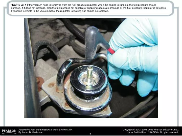
FIGURE 23–1 If the vacuum hose is removed from the fuel-pressure regulator when the engine is running, the fuel pressure should increase. If it does not increase, then the fuel pump is not capable of supplying adequate pressure or the fuel-pressure regulator is defective. If gasoline is visible in the vacuum hose, the regulator is leaking and should be replaced.
FIGURE 23–2 (a) A fuel-pressure graph after key on, engine off (KOEO) on a TBI system. (b) Pressure drop after 10 minutes on a normal port fuel-injection system.
FIGURE 23–3 A clogged PCV system caused the engine oil fumes to be drawn into the air cleaner assembly. This is what the technician discovered during a visual inspection.
FIGURE 23–4 All fuel injectors should make the same sound with the engine running at idle speed. A lack of sound indicates a possible electrically open injector or a break in the wiring. A defective computer could also be the cause of a lack of clicking (pulsing) of the injectors.
FIGURE 23–5 Fuel should be heard returning to the fuel tank at the fuel return line if the fuel-pump and fuel-pressure regulator are functioning correctly.
FIGURE 23–6 Using a scan tool to check for IAC counts or percentage as part of a diagnostic routine.
FIGURE 23–7 Checking the fuel pressure using a fuelpressure gauge connected to the Schrader valve.
FIGURE 23–8 Shutoff valves must be used on vehicles equipped with plastic fuel lines to isolate the cause of a pressure drop in the fuel system.
FIGURE 23–9 (a) Noid lights are usually purchased as an assortment so that one is available for any type or size of injector wiring connector. (b) The connector is unplugged from the injector and a noid light is plugged into the injector connector. The noid light should flash when the engine is being cranked if the power circuit and the pulsing to ground by the computer are functioning okay.
FIGURE 23–10 Use a DMM set to read DC volts to check the voltage drop of the positive circuit to the fuel injector. A reading of 0.5 volt or less is generally considered to be acceptable.
FIGURE 23–11 Connections and settings necessary to measure fuel-injector resistance.
FIGURE 23–12 To measure fuel-injector resistance, a technician constructed a short wiring harness with a double banana plug that fits into the V and COM terminals of the meter and an injector connector at the other end. This setup makes checking resistance of fuel injectors quick and easy.
FIGURE 23–13 (a) The meter is connected to read one group of three 12-ohm injectors. The result should be 4 ohms and this reading is a little low indicating that at least one injector is shorted (low resistance). (b) This meter is connected to the other group of three injectors and indicates that most, if not all three, injectors are shorted. The technician replaced all six injectors and the engine ran great.
FIGURE 23–14 If an injector has the specified resistance, this does not mean that it is okay. This injector had the specified resistance yet it did not deliver the correct amount of fuel because it was clogged.
FIGURE 23–15 Connect a fuelpressure gauge to the fuel rail at the Schrader valve.
FIGURE 23–16 An injector tester being used to check the voltage drop through the injector while the tester is sending current through the injectors. This test is used to check the coil inside the injector. This same tester can be used to check for equal pressure drop of each injector by pulsing the injector on for 500 ms.
FIGURE 23–17 A digital storage oscilloscope can be easily connected to an injector by carefully back probing the electrical connector.
FIGURE 23–18 The injector on-time is called the pulse width. (Courtesy of Fluke Corporation)
FIGURE 23–19 A typical peak-and-hold fuel-injector waveform. Most fuel injectors that measure less than 6 ohms will usually display a similar waveform.
FIGURE 23–20 A set of six reconditioned injectors. The sixth injector is barely visible at the far right.
FIGURE 23–21 An IAC controls idle speed by controlling the amount of air that passes around the throttle plate. More airflow results in a higher idle speed.
FIGURE 23–23 Some IAC units are purchased with the housing as shown. Carbon buildup in these passages can cause a rough or unstable idling or stalling.
FIGURE 23–24 (a) Nothing looks unusual when the hood is first opened. (b) When the cover is removed from the top of the engine, a mouse or some other animal nest is visible. The animal had already eaten through a couple of injector wires. At least the cause of the intermittent misfire was discovered.
FIGURE 23–25 Checking fuel-pump volume using a hose from the outlet of the fuel-pressure regulator into a calibrated container.
FIGURE 23–26 Testing fuel-pump volume using a fuelpressure gauge with a bleed hose inserted into a suitable container. The engine is running during this test.
FIGURE 23–27 A typical two-line cleaning machine hookup, showing an extension hose that can be used to squirt a cleaning solution into the throttle body while the engine is running on the cleaning solution and gasoline mixture.
FIGURE 23–28 To thoroughly clean a throttle body, it is sometimes best to remove it from the vehicle.