Download

1 / 15
150 likes | 158 Vues
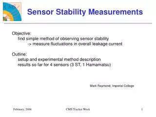
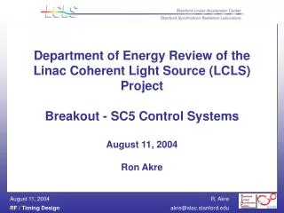
Kicker stability and flatness measurements. F. Obier , W. Decking, B. Faatz, M. Hüning, J. Kahl, J. Klute, K. Müller, J. Wortmann. Workshop on Linac Operation with Long Bunch Trains Hamburg, June 08, 2011. Specification. Principle layout of beam distribution. Power supply 3. Power supply 2.

E N D
Kicker stability and flatness measurements F. Obier, W. Decking, B. Faatz, M. Hüning, J. Kahl, J. Klute, K. Müller, J. Wortmann Workshop on Linac Operation with Long Bunch Trains Hamburg, June 08, 2011
Principle layout of beam distribution Power supply 3 Power supply 2 Power supply 1 Septum Pulser 3 Pulser 2 Pulser 1 2mrad 10mm ACC7 Kicker 1 Kicker 3 Kicker 2 6.8m FLASH II Emax = 450MeV - 1,6GeV f = 10Hz tlücke = 10-50μs tpuls = 0-1000μs LCeramic = 0.7m (flange to flange) DCeramic = 38mm (inside) 46mm (outside) LKicker = 0,6m Stability = 3*10-4 or 0.6μrad
pulse trigger Principle layout of the pulser 200A Power supply Data: Voltage U= 80V Pulse current Imax=400A Pulse length t= 1.8ms Pulse current CLade 200µs/div 50A/div +5V L Kicker -5V D G - + S Op-amp AD817 S R • 8 Mosfet parallel • 9 capacitor (450V 2200µF) Constant current source
Rise and fall time of the pulse current Rise time = 10µs Fall time =14µs
PSI Feedbackkicker • Kicker design: • a strip line kicker inside of vacuum • a small reflectance factor, to match the kicker impedance to 50 ohm. • with the geometry of the conductor, and the distance between the conductor and the cage you can match the kicker impedance to 50Ω.
Feedbackkicker • strip line kicker outside of vacuum • the Kicker was built in a 50 geometry • ceramic vacuum chamber • coating material is stainless steel 4.4541 (titan stabilised) • a small reduction of the magnetic field by the sputtered chamber.
A principle set up of the pulser test at FLASH Data: Beam energy 680MeV Voltage U= 80V Pulse current I=40A Pulse length t= 1.8ms Correktion coils Gun ACC7 Feedbackkicker BPM 1SFUND3 Timing System Pulser • For this test we used the installed feedbackkicker • measure the pulse flatness, stability of kicker pulse and kicker strength • scan the kicker pulse with a step width of 10µs and taking 10 pulses for each data point.
Result of scan at FLASH • Puls current: 8.5A • Puls length: 600 μs • Adjustment at Flash: • Energy Feedback off • Scan-change in direction • Read –out all BPMs BPM [mm] delay [ms] • Measurement with 4 BPM’s • All BPM show the same characteristics • Deviation from pulse flatness • Very slow fall time • Why?
Effect of different bunch charge Puls current: 8,5A Puls length: 600 μs Beam throughUndulator • The same performanceof the kick amplitude • No effect of the bunch charge
Scan with different kickermagnets horizontal Feedbackkicker (PSI) strip line kicker inside of vacuum vertikaler Feedbackkicker strip line kicker outside of vacuum 40A 1168MeV 40A 1800 μs 1800 μs 683MeV • The different designs of kicker has an effect of the droop, rise and fall time
Flatness measurements at FLASH 200µs/div Pulse current 190A . Bunch train 600µs 400µs 200µs 1500µs • Bunch train with 30 Bunche • Bunch spacing of 4µs (250kHz) • to shift the bunch train with a delay of 100µs and to look the variation of the SASE-level • switch on kicker and adjust the beam position with a steerer • On the top we have a area of 400µs with no variation of the SASE-level • After the trading edge we have up to 1.5ms a variation of the SASE-level
Conductor Probe (fixed) Trigger Puls Scope Trigger source Pulser Current The measurement of the magnetic field Chamber • Measurement with different magnetic sensors • The goal: optimisation of the kicker geometry in order to achieve high field strength and the deviation from pulse flatness
Result of the magnetic field measurement Air-core coil (1 winding) with integrator CMR Sensor Feedbackkicker without cage Current 100A 200µs/div 50A/div Current 200A Feedbackkicker with cage 20A/div 200µs/div Feedbackkicker without cage • green curve: pulse current of 200A • white curve: field measurement with a Feedbackkicker without cage (with a droop and a very slow fall time of 1ms) • Yellow curve: field measurement with a Feedbackkicker with cage (no droop and a fast fall time) • green curve: pulse current of 100A • Yellow curve: field measurement with a Feedbackkicker with cage (with a droop and a very slow fall time of 1ms) • grey curve: field measurement with a Feedbachkicker without cage (no droop and a fast fall time) Feedbackkicker with cage • Result: The eddy current on the kicker cage create the droop and a very slow fall time.
Summary / outlook • Pulse to pulse stability is for SASE ok • We want to optimise the kicker geometry and magnetic field • The stability and the flatness should be remeasured with beam at FLASH (June15, 2011)