Download
1 / 50
560 likes | 1.43k Vues
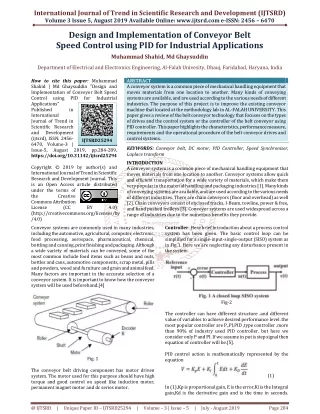
Choosing and using LEL, PID and NDIR Sensors and Applications. Bob Henderson President GfG Instrumentation 1194 Oak Valley Drive Ann Arbor, MI 48108 Toll free: (800) 950-0329 Direct: (734) 769-0573 Fax: (734) 769-1888 E-mail: info@gfg-inc.com Internet: www.gfg-inc.com.

E N D
Choosing and using LEL, PID and NDIR Sensors and Applications Bob Henderson President GfG Instrumentation 1194 Oak Valley Drive Ann Arbor, MI 48108 Toll free: (800) 950-0329 Direct: (734) 769-0573 Fax: (734) 769-1888 E-mail: info@gfg-inc.com Internet: www.gfg-inc.com
Learning Objectives • Capabilities and limitations of LEL, infrared (NDIR) and photoionization (PID) sensors • Using EC toxic sensors for the new toxic exposure limits for H2S and SO2
Traditional EC Toxic and Combustible Pellistor sensors • More types of sensors available every year, both for individual toxic gases as well as sensors designed to detect a range of toxic or combustible gases
Substance-specific electrochemical sensors • Gas diffusing into sensor reacts at surface of the sensing electrode • Sensing electrode made to catalyze a specific reaction • Use of selective external filters further limits cross sensitivity
Exposure limits for H2S • Old TLV: • TWA = 10 ppm • STEL = 15 ppm • New TLV: • TWA = 1.0 ppm • STEL = 5.0 ppm 4 4 0
FR VL UK OEL DFG MAK TLV (2010) 10 ppm 5 ppm 10 ppm 10 ppm 1.0 ppm 5.0 ppm 15 ppm NA NA NA NA NA NA Exposure limits for H2S Federal USA OSHA PEL 8-Hour TWA STEL Acceptable Ceiling Concentration Acceptable Max Peak Above Ceiling for an 8-Hour Shift Concentration Maximum Duration 10-minutes once only if no other measurable exposure occurs during shift NA 20 ppm NA 50 ppm 10 ppm 15 ppm NA NA NA REL NA NA NA NA 20 ppm peak in any 10-min period, (as momentary ceiling value), maximum 4 per shift
Electrochemical H2S Sensor Detection Mechanism Hydrogen sulfide is oxidized at the sensing electrode: H2S + 4H2O H2 SO4 + 8H+ + 8e- The counter electrode acts to balance out the reaction at the sensing electrode by reducing oxygen present in the air to water: 2O2 + 8H+ + 8e- 4H2O And the overall reaction is: H2S + 2O2H2 SO4 4HS Signal Output: 0.7 A / ppm H2S Resolution of sensor approximately 0.2 ppm
Effects of humidity on EC sensors • Sudden changes in humidity can cause "transientys" in readings • Sensor generally stabilizes rapidly • Avoid breathing into sensor or touching with sweaty hand
Effects of temperature on EC sensors • Effects of temperature on output significant, but predictable • Generally, only need to zero the sensor once the instrument has stabilized at the new temperature • Usually not necessary to span adjust the sensor
Exposure limits for SO2 • Old TLV : • TWA = 2 ppm • STEL = 5 ppm • New (2009) TLV: • STEL = 0.25 ppm • Sensor capable of 0.05 ppm resolution 0 3 0
Exposure limits for NO2 • TLV: • 8 hr. TWA = 3 ppm • 15 min. STEL = 5 ppm • US OSHA PEL: • Ceiling = 5 ppm • US NIOSH REL: • 15 min. STEL = 1 ppm • Sensor capable of 0.1 ppm resolution 0 3 0 OX
Catalytic “Hot Bead” Combustible Sensor • Detects combustible gas by catalytic oxidation • When exposed to gas oxidation reaction causes "active" bead in sensor to heat • Requires oxygen to detect gas!
Stainless steel housing Flame arrestor (sinter) Traditional LEL sensors are “Flame proof” devices • Flame proof sensors depend on physical barriers such as stainless steel housings and flame arrestors to limit the amount of energy that can ever be released by the sensor • The flame arrestor can slow, reduce, or even prevent larger molecules from entering the sensor • The larger the molecule, the slower it diffuses through the flame arrestor into the sensor
Porous refractory bead with catalyst Platinum wire coil 0.1 mm Catalytic “Hot Bead” Structure Active (pellistor) and reference compensator) beads PTFE Mounting Disc PCB Board
Typical carbon number distribution in No. 2 Diesel Fuel (liquid)
CH4 response new sensor Propane response Response to nonane Using a lower alarm setting minimizes effect of relative response on readings Instrument Reading 50% LEL 20% LEL 10% LEL 5% LEL True LEL Concentration
Combustible sensor limitations Flashpoint Temp (ºF) 5% LEL in PPM Contaminant LEL (Vol %) OSHA PEL NIOSH REL TLV 500 PPM TWA; 750 PPM STEL 1,000 PPM TWA Acetone 2.5% -4ºF (-20 ºC) 250 PPM TWA 1250 PPM Diesel (No.2) vapor 0.6% 125ºF (51.7ºC) None Listed None Listed 15 PPM 300 PPM Ethanol 3.3% 55ºF (12.8 ºC) 1,000 PPM TWA 1000 PPM TWA 1000 PPM TWA 1,650 PPM 300 PPM TWA; 500 PPM STEL Gasoline 1.3% -50ºF (-45.6ºC) None Listed None Listed 650 PPM n-Hexane 1.1% -7ºF (-21.7 ºC) 500 PPM TWA 50 PPM TWA 50 PPM TWA 550 PPM Isopropyl alcohol 2.0% 53ºF (11.7ºC) 400 PPM TWA 400 PPM TWA; 500 PPM STEL 200 PPM TWA; 400 PPM STEL 1000 PPM 100 mg/M3 TWA (approx. 14.4 PPM) Kerosene/ Jet Fuels 0.7% 100 – 162ºF (37.8 – 72.3ºC ) None Listed 200 mg/M3 TWA (approx. 29 PPM) 350 PPM 200 PPM TWA; 300 PPM STEL MEK 1.4% 16ºF (-8.9ºC) 200 PPM TWA 200 PPM TWA; 300 PPM STEL 700 PPM Turpentine 0.8 95ºF (35ºC) 100 PPM TWA 100 PPM TWA 20 PPM TWA 400 PPM 100 PPM TWA; 150 PPM STEL 100 PPM TWA; 150 STEL Xylenes (o, m & p isomers) 0.9 – 1.1% 81 – 90ºF (27.3 – 32.3 ºC) 100 PPM TWA 450 – 550 PPM
Limitations of catalytic pellistor LEL sensors • Flame arrestor limits molecules larger than nine carbons (nonane) from entering sensor • Even when molecules are able to diffuse into sensor: the larger the molecule the lower the relative response, and the slower the sensor responds • Easily poisoned • Exposure to high concentration combustible gas damaging to sensor • Requires oxygen to detect gas!
Response of electrochemical and LEL sensor to 21,000 ppm hydrogen in nitrogen
Relative response of CO sensor to 21,000 ppm hydrogen in nitrogen 1,000 ppm CO (over-range limit concentration of sensor installed)
Combustible sensor poisons • Combustible sensor poisons: • Silicones (by far the most virulent poison) • Hydrogen sulfide • Other sulfur containing compounds • Phosphates and phosphorus containing substances • Lead containing compounds (especially tetraethyl lead) • High concentrations of flammable gas! • Combustible sensor inhibitors: • Halogenated hydrocarbons (Freons, trichloroethylene, methylene chloride, etc.)
CH4 response new sensor Propane response CH4 response partially poisoned sensor Response to methane over life of sensor • Relative response to methane may change substantially over life of sensor
Non-dispersive infrared (NDIR) sensors • Many gases absorb infrared light at a unique wavelength (color) • In NDIR sensors the amount of IR light absorbed is proportional to the amount of target gas present • The longer the optical path through the semnsor the better the resolution
Electromagnetic radiation spectrum Infrared (IR) region covers the wavelength range from approx. 0.7 µm to 100 µm More than 100 times as wide as the visible portion!
Infrared absorption spectra for several gases Gas absorption spectra Methane CH4 Propane C3H8 T Water H2O Carbon dioxide CO2 l [nm]
T l [nm] Two and three wavelength NDIR sensors • Simultaneous measurement CO2 and combustible gas • LEL: 3.3 μm • CO2: 4.3μm • Ref: 4.0μm 3.3μm 4.0 μm 4.3 μm
Infrared Spectroscopy • Geometry of molecule and absorbance of light by specific bonds gives rise to a characteristic IR absorbance “fingerprint” of molecule
Requirements for IR Absorption • CO2 and CH4 as well as most other combustible gasesabsorb IR • Hydrogen gas ( H2 ) DOES NOT absorb IR • While acetylene absorbs IR, it is also effectively undetectable at 3.3 μm • Also IR-transparent: • N2 • O2 • F2 • Cl2 • Hg2 • Ar
Relative response of pellistor and infrared sensors to n-Hexane • Both sensors were calibrated to 50% LEL methane • Uncorrected readings for the pellistor LEL sensor much lower than the true concentration • Uncorrected readings for the IR sensor more than twice as high as the true concentration 50% LEL n-Hexane
50% LEL n-Hexane Response of calibrated pellistor and IR sensors to 50% LEL n-Hexane • Both sensors were calibrated to 50% LEL n-Hexane • Readings for both sensors are now very close to the true 50% LEL concentration • Initial response of IR sensor is slightly quicker than the pellistor sensor • However, the time to the final stable response (T100) is virtually identical for both sensors, (about 150 seconds)
Relative response of CO sensor to 21,000 ppm hydrogen in nitrogen 1,000 ppm CO (over-range limit concentration of sensor installed)
Photoionization Detectors • Used for measuring solvent, fuel and VOC vapors in the workplace environment
LEL vs. PID Sensors • Catalytic LEL and PID sensors are complementary detection techniques • Catalytic LEL sensors excellent for methane, propane, and other common combustible gases that are NOT detectable by PID • PIDs detect large VOC and hydrocarbon molecules that are undetectable by hot-bead sensors • Best approach is to use multi-sensor instrument that includes both types of sensors
Choosing the best sensor configuration • Multi-sensor instruments can include up to seven channels of real-time measurement • Available sensors for combustible gas and VOC measurement:: • CC %LEL • IR %LEL • IR %Vol • Thermal Conductivity %Vol • Electrochemical toxic • PID
PID, CC LEL, IR LEL and CO sensors exposed to 50% LEL acetylene (1.25% volume)
PID, CC LEL, IR LEL and CO sensors exposed to 50% LEL isobutylene (9,000 ppm) The maximum full-range reading for the G460 PID is 3,000 ppm (= 17.5% LEL Isobutylene). Readings at or above this concentration are logged at the maximum value
PID, CC LEL, IR LEL and CO sensors exposed to denatured alcohols vapor See following PPT slide for explanation of graphs
Explanation of response curves in Slide 45: PID, CC LEL, IR LEL and CO sensors exposed to denatured alcohols vapor • IR %LEL response curve (Red): • Sensor responds very rapidly to alcohol vapor • Maximum full-range reading for G460 IR LEL sensor is 150% LEL • Readings at or above this concentration logged at the maximum value • IR sensor resumes logging concentration when readings drop below 150% LEL • Catalytic %LEL response curve (Dark Blue): • CC LEL sensor responds much more slowly than the IR LEL sensor • At 150% LEL instrument "latches" the over-limit alarm, and cuts power to the active bead to avoid damage to the sensor • Readings at or above this concentration logged at the maximum value • CC %LEL sensor must be manually reset to return to normal operation • Graph shows 43 second warm-up period after manually resetting the sensor • CO sensor response curve (Green): • CO sensor did not begin to show readings until after exposure to alcohol was ended • CO readings eventually climbed reached the 500 ppm "over limit" concentration • Took over four hours for CO sensor to recover and stabilize at fresh-air value
Test run# 1: PID, CC LEL, IR LEL and CO sensors exposed to diesel vapor
Test run# 4: PID, CC LEL, IR LEL and CO sensors exposed to diesel vapor
Selection matrix for Sensors for measurement of combustible gas and VOCs