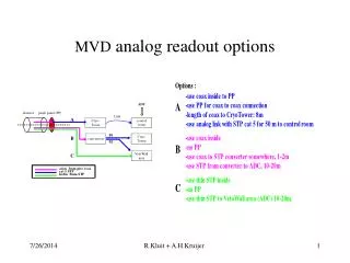
Download
1 / 19
190 likes | 354 Vues
ANALOG AND DIGITAL PROCESSING FOR THE READOUT OF RADIATION DETECTORS. J.C. Santiard, CERN, Geneva, CH (jean-claude.santiard@cern.ch) K. Marent, IMEC vzw, 3001 Leuven, BE (marentk@imec.be) H. Witters, IMEC vzw, 3001 Leuven, BE (witters@imec.be) J. Hauser, CMS UCLA Sh. Chandramouly, CMS UCLA.

E N D
ANALOG AND DIGITAL PROCESSING FOR THE READOUT OF RADIATION DETECTORS • J.C. Santiard, CERN, Geneva, CH (jean-claude.santiard@cern.ch) • K. Marent, IMEC vzw, 3001 Leuven, BE (marentk@imec.be) • H. Witters, IMEC vzw, 3001 Leuven, BE (witters@imec.be) • J. Hauser, CMS UCLA • Sh. Chandramouly, CMS UCLA J.C Santiard CERN EP-MIC
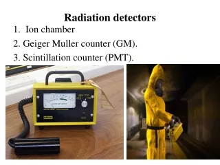
CERN EP-MIC LONG P.T. ANALOG FRONT-END DEVELOPMENT • Long peaking-time(.5 s; 1.2 s) used as delay, waiting for a trigger to memorize on cap. by T/H; multiplexed output. • General use • 1987 AMPLEX 3m tech. 60 wafers • 1990 AMPLEX-SICAL 3m tech. 100 wafers • Gaseous detectors • 1993 GASPLEX 1.5m tech. 10 wafers • 1994 GASSIPLEX1.5 1.5m tech. (Si) 60 wafers • 1998 GASSIPLEX0.7 0.7m tech. (Si) Proto. J.C Santiard CERN EP-MIC
Ions drift time of several tens of s from anode to cathode: i(t) = I0B/(1 + t/t0) q(t) = Q0ALn (1 + t/t0) A, B and t0 are constants depending on detector geometry and electric field. Filtering adaptable to any kind of drift time SIGNAL PROCESSING FOR GASEOUS DETECTORS J.C Santiard CERN EP-MIC
CONTINUOUS TIME DECONVOLUTION FILTER • GOAL:RECREATE A STEP FUNCTION FROM THE LOGARITHMIC SHAPE OF THE CHARGE OR A DIRAC PULSE FROM THE CURRENT SIGNAL. • Impulse response of detector model with Dirac input: • h(t) = U(t)/(t0+t) U(t) is a step function • function of the deconvolver G(s) should be: • G(s) = H(s)-1 H(s) = L[ h(t) ] • 3 exponentials in the feedback of a summing amplifier: • G(s) = Vout/Vin = A/(1 + A) ; if A>>, G(s) ~ 1/ J.C Santiard CERN EP-MIC
3 weighted exponential: = K1/(1 + sT1) + K2/(1 + sT2) + K3/(1 + sT3) Gain factors: K1 = 0.2; K2 = 0.3; K3 = 0.5 Time constants: T1 = C1/gm1 ; T2 = C2/gm2 ; T3 = C3/gm3 PRACTICAL IMPLEMENTATION J.C Santiard CERN EP-MIC
ACTIVE FEEDBACK RESISTOR • Rf = 20 M J.C Santiard CERN EP-MIC
POLE/ZERO CANCEL. RESISTOR • Rp/z = 2.2 M J.C Santiard CERN EP-MIC
SHAPER • NO DIFFERENTIATING CAPACITOR J.C Santiard CERN EP-MIC
CSA OUTPUT FILTER OUTPUT SHAPER OUTPUT SIMULATIONS RESULTS J.C Santiard CERN EP-MIC
LAYOUT J.C Santiard CERN EP-MIC
NOISE Vs Cin GAIN SPREAD MEASUREMENTS J.C Santiard CERN EP-MIC
LINEARITY J.C Santiard CERN EP-MIC
CALIBRATION J.C Santiard CERN EP-MIC
SHAPING ON GASEOUS DETECTOR PAD WITH 55Fe Xray SOURCE J.C Santiard CERN EP-MIC
TABLE OF RESULTS(1) • Technology MIETEC-0.7m • Silicon area 3.63 x 4 = 14.5 mm2 • Silicon detector mode • Gain 2.2 mV/fC • Dynamic range ( + ) 900 fC ( 0 to 2 V) • Dynamic range ( - ) 500 fC ( 0 to -1.1 V) • Non linearity 3 fC • Noise at 0 pF 600 e- rms • Noise slope 12 e- rms/pF • Low power mode • Power consumption 4mW/chan. at 4 MHz • Noise at 0 pF 600 e- rms • Noise slope 15 e- rms/pF J.C Santiard CERN EP-MIC
TABLE OF RESULTS(2) • Gaseous detector mode • Peaking time 1.2 s • Peaking time adjust. 1.1 to 1.3 s • Noise at 0 pF 530 e- rms • Noise slope 11.2 e- rms/pF • Dynamic range ( + ) 560 fC ( 0 to 2 V ) • Dynamic range ( - ) 300 fC ( 0 to -1.1 V ) • Gain 3.6 mV/fC • Non linearity 2 fC • Baseline recovery .5% after 5 s • Analog readout speed 10MHz (50 pF load) • Power consumption 8mW/chan. at 10 MHz • Out. Temp. coeff. 0.05 mV/0C J.C Santiard CERN EP-MIC
BLOCK DIAGRAM J.C Santiard CERN EP-MIC
CHARACTERISTICS: 16 TO 64 CHANNELS PED. SUBTRACTION ZERO SUPPRESSION 512X18 BITS DATA FIFO 64X16 BITS BITMAP FIFO 4 BITS CONTROLLER ASYNCHRONOUS R/W FIFO FLAGS PROTOTYPES DELIVERY: OCT. 99 DILOGIC2: A SPARSE DATA SCAN READOUT PROCESSOR J.C Santiard CERN EP-MIC
16-Ch. LCT-COMP • USE ON THE CSC ENDCAP MUON DETECTORS IN CMS TO LOCALIZE THE TRACK HIT POSITION TO 1/2 STRIP. • COMPARATORS HAVE LOW OFFSET SPREAD: <.9mv rms. • SPATIAL RESOLUTION DEPEND MAINLY ON THE INPUT NOISE LEVEL. • ON-CHAMBER TESTING WILL BE DONE DURING SUM. 00 • PRE-PRODUCTION WILL START IN MARCH 00 J.C Santiard CERN EP-MIC