Download
1 / 52
520 likes | 527 Vues
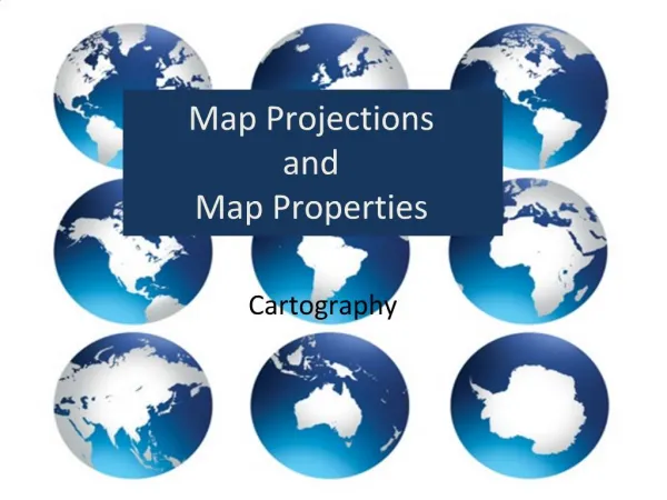
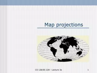
This article explains the different types of map projections and coordinate systems used to represent the curved Earth on flat maps. It discusses the concept of distortion, true directions, angles, distances, and areas, as well as the use of geodetic datums. It also provides an overview of various projection families and their characteristics.

E N D
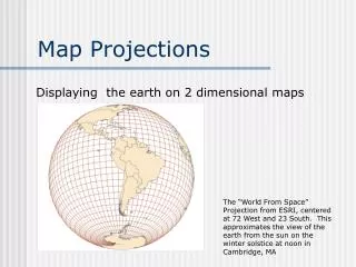
flat Earth is curved Maps are flat
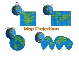
Map Distortion • No map is as good as a globe. • A map can show some of these features • True direction or azimuth • True angle • True distance • True area • True shape But not all of them!
Coordinate System common frame of reference for all data on a map
GIS needs Coordinate Systems to: • perform calculations • relate one feature to another • specify position in terms of distances and directions from fixed points, lines, and surfaces
Coordinate Systems Cartesian coordinate systems: perpendicular distances and directions from fixed axes define positions Polar coordinate systems:distance from a point of origin and an angle define positions
Each coordinate system uses a different model to map the Earth’s surface to a plane
GCSGeographic Coordinate Systems • Degrees of latitude and longitude • Spherical polar coordinate system • “Real” distance varies
Spherical Coordinates • Any point uniquely defined by angles passing through the center of the sphere Meridian Equator
The Graticule • Map grid (lines of latitude and longitude) • A transformation of Earth’s surface to a plane, cylinder or cone that is unfolded to a flat surface
Decimal Degrees 30º 30' 0" = 30.5º 42º 49' 50" = 42.83º 35º 45' 15" = ? 35.7541
Parallels of Latitude Equator Slicing the Earth into pieces
Measuring Parallels Give the slices values
Lines of Longitude Antimeridian A Meridian A Establish a way of slicing the Earth from pole to pole
Prime Meridian Establishes an orthogonal way of slicing the earth
Longitude North America Values of pole-to-pole slices
Earth Grid Comparing the parallels and the lines
Latitude and Longitude Combining the parallels and the lines
Grid for US What is wrong with this map? Parallels and Lines for US
Sphere vs. Ellipsoid Globes versus Earth
Shape of the Earth • Approximated by an ellipsoid • Rotate an ellipse about its minor axis = earth’s axis of rotation • Semi-major axis a = 6378 km • Semi-minor axis b = 6356 km NP b a SP
Ellipsoids and Geoids • The rotation of the earth generates a centrifugal force that causes the surface of the oceans to protrude more at the equator than at the poles. • This causes the shape of the earth to be an ellipsoid or a spheroid, and not a sphere. • The nonuniformity of the earth’s shape is described by the term geoid. The geoid is essentially an ellipsoid with a highly irregular surface; a geoid resembles a potato or pear.
The Ellipsoid The ellipsoid is an approximation of the Earth’sshape that does not account for variations caused by non-uniform density of the Earth. Examples
Satellite measurements have led to the use of geodetic datums WGS-84 (World Geodetic System) and GRS-1980 (Geodetic Reference System) as the best ellipsoids for the entire geoid.
The Geoid • The maximum discrepancy between the geoid and the WGS-84 ellipsoid is 60 meters above and 100 meters below. • Because the Earth’s radius is about 6,000,000 meters (~6350 km), the maximum error is one part in 100,000.
Geodetic Datum • Defined by the reference ellipsoid to which the geographic coordinate system is linked • The degree of flattening f (or ellipticity, ablateness, or compression, or squashedness) • f = (a - b)/a • f = 1/294 to 1/300
Geodetic Datums • A datum is a mathematical model • Provide a smooth approximation of the Earth’s surface. • Some Geodetic Datums
Common U S Datums • NAD27 North American Datum 1927 • NAD83 North American Datum 1983 • WGS84 World Geodetic System 1984 (based on NAD83)
Making a Map Concept of the Light Source
Azimuthal Projections • Shapes are distorted everywhere except at the center • Distortion increases from center • True directions can be plotted from the center outward • Distances are accurate from the center point
Polyconic Projections • A series of conic projections stacked together • Have curved rather than straight meridians • Not good choice for tiles across large areas
Albers Conic Equal AreaProjections • Good choice for mid-latitude regions of greater east-west than north-south extent • Scale factor along two standard parallels is 1.0000 • Scale is reduced between the two standard parallels and increased north or south of the two standard parallels
Equal Area Projections • Projections that preserve area are called equivalent or equal area. • Equal area projections are good for small scale maps (large areas) • Examples: Mollweide and Goode • Equal-area projections distort the shape of objects
Conformal Map Projections • Projections that maintain local angles are called conformal. • Conformal maps preserve angles • Conformal maps show small features accurately but distort the shapes and areas of large regions • Examples: Mercator, Lambert Conformal Conic
Conformal Map Projections • The area of Greenland is approximately 1/8 that of South America. However on a Mercator map, Greenland and South America appear to have the same area. • Greenland’s shape is distorted.
Map Projections • For a tall area, extended in north-south direction, such as Idaho, you want longitude lines to show the least distortion. • You may want to use a coordinate system based on the Transverse Mercator projection.
Map Projections • For wide areas, extending in the east-west direction, such as Nebraska, you want latitude lines to show the least distortion. • Use a coordinate system based on the Lambert Conformal Conic projection.
Map Projections • For a large area that includes both hemispheres, such as North and South America, choose a projection like Mercator. • For an area that is circular, use a normal planar (azimuthal) projection
Universal Transverse Mercator • 1940s, US Army • 120 zones (coordinate systems) to cover the whole world • Based on the Transverse Mercator Projection • Sixty zones, each six degrees wide
UTM Zones • Zone 1 Longitude Start and End 180 W to 174 W Linear Units Meter False Easting 500,000 False Northing 0 Central Meridian 177 W Latitude of Origin Equator Scale of Central Meridian 0.9996