Download
1 / 25
250 likes | 359 Vues
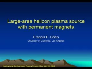
Commercial helicon sources inject plasma into a field-free region. The MORI source. A helicon injection expt. We wish to optimize a source which could be part of a large array. Metal or ceramic endplate. Arbitrary antenna.

E N D
Commercial helicon sources inject plasma into a field-free region The MORI source A helicon injection expt.
We wish to optimize a source which could be part of a large array Metal or ceramic endplate Arbitrary antenna We can use a low-field density peak seen in at B 30G for n 1012 cm-3
The low-B peak has been seen in many different experiments 1989, 1" tube The field at the peak can range between 10 and 50G, and the peak is much larger in some experiments than in others.
The low-B peak is also seen in a 7-tube array of m = 0 sources 8 mTorr, 13.56 MHz
Computations using Don Arnush's HELIC code predict this peak and show how it varies • HELIC calculates waves and loading with • Radial density profile n(r) • Collisional damping • Different (thin) antenna configurations • Antenna coupling • Trivelpiece-Gould modes • Endplates (arbitrary reflectivity) • It requires • Uniform B-field • Uniform n(z) • • Cold-plasma dielectric
The plasma loading R() shows a low-B peak which moves with density 1011-1012 range Single-loop m = 0 antenna, 10 cm from endplate, 2 mTorr, Te = 4eV
At high densities, the low-B peak is gone 1012-1013 range Single-loop m = 0 antenna, 10 cm from endplate, 2 mTorr, Te = 4eV
The low-B peak vs. density at constant B Single-loop m = 0 antenna, 10 cm from endplate, 2 mTorr, 13.56 MHz
What is the cause of the low-B peak? • It is not the lower hybrid resonance (1450 G) • Is it due to a resonance between the helicon mode and the Trivelpiece-Gould mode, when they have comparable radial wavelengths and can interfere constructively? • Is it due to constructive interference by the wave reflected from the endplate? Computations show that it is probably the latter.
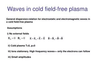
"Standard" conditions for numerical tests B = 10-300 G no = 1012 cm-3 p = 10 mTorr Ar Insulating endplate KTe = 4 eV (affects collisions only) f = 13.56 MHz Radial density profile
The peak depends on the type of antenna Single loop: m = 0, bidirectional HH (half-wavelength helical): m = 1, undirectional Nagoya Type III: m = 1, bidirectional
Axial deposition profile of HH10 antenna depends on the sign of the helicity Direction of propagation: (m = +1), (m = -1)
This explains previous data on density enhancement by an aperture limiter Block can be solid or have a 1.2-cm diam hole. It can be conducting (carbon) or insulating (boron nitride). It can be moved to various positions behind or under the antenna.
Radial density profile shows enhancement whenever there is a limiter
The end coils can also be turned off or reversed to form a cusped B-field The field lines then end on the glass tube, which forms an insulting endplate. An aperture limiter can also be added.
Limiter enhancement with and without a magnetic cusp The cusp field greatly enhances the density without a limiter, but adds little when a limiter is already in place.
Density increase with end coil current is larger with a bidirectional antenna
CONCLUSION For low-field, low-density helicon injection into a large chamber, reflection of waves from an endplate can be designed to optimize plasma production. This phenomenon is probably responsible for previously unexplained density increases with aperture limiters and cusped magnetic fields . This is a significant effect.