Download
1 / 22
240 likes | 414 Vues
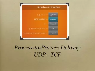
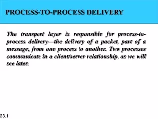
Section 23.1 Process-to-process delivery. Client/server paradigm Port numbers Sockets Plus a few other definitions We’ve covered most of this. TCP section 23.3. Layer 4 protocol Connection oriented (virtual connection) TCP segment ( embedded in an IP packet ) looks like.

E N D
Section 23.1 Process-to-process delivery • Client/server paradigm • Port numbers • Sockets • Plus a few other definitions • We’ve covered most of this
TCP section 23.3 • Layer 4 protocol • Connection oriented (virtual connection) • TCP segment (embedded in an IP packet) looks like
Most fields have been described previously • Bit fields and the urgent pointer are used to identify data that needs special handling. • See book for more detail.
Three-way handshake • Client and server exchange packets to set up a connection. • Packets also identify some parameters for the connection. • For example, TCP uses a sliding window protocol but counts bytes instead of segments.
Figure 23.18 Connection establishment using three-way handshaking
Data transfer • Very similar to what we did when discussing flow control (go-back-n and selective repeat) protocols. • Two differences: • The protocol numbers the bytes in a stream instead of packets. • Protocol can increase and decrease the sending window size dynamically.
Congestion control (congestion window) – section 24.4 • A receiver can tell the sender to increase or decrease its window size depending on the receiver’s ability to handle the data. • If segments are timing out a lot, the sender might suspect there’s some congestion in the network. It can then reduce the flow of new segments into the network. • If acks are coming back quickly the sender suspects it might be able to increase the flow of new segments.
window size = MIN {receiver window size, size of congestion window). • This latter value can vary (we’ll see how) • If congestion window is large => no change from before.
Suppose timeouts occur on outstanding segments. • If caused by congestion (usually the case, since reliability is high), resending them adds to it. • In this case, cut congestion window in half and resend segments in the new window. • Repeat above as often as needed (minimum congestion window would contain 1 segment)
If congestion clears • If all segments are ack’d, increase congestion window by 1 segment • Repeat until the window hits a max value • Initialization • congestion window = 1 segment. • If no timeouts occur, double it for the next set of segments. • Keep doubling until timeouts occur or receiver window size is reached.
Figure 23.20 Connection termination using three-way handshaking
no connection established - Connectionless • No flow control, limited error checking. • Simple, minimum overhead • Useful for sending short messages where reliability is less of a concern
Example • traceroutecommand causes the following actions: • Source creates a UDP probe packet with an unused port number. • It puts it in an IP packet with a TTL value of 1 and sends it to the destination.
The first router decreases the TTL value and, seeing it is 0, replies with an ICMP (Internet Control Message Protocol) time exceeded packet. • The source gets this reply and records the router address and the round-trip time. • The source creates another similar UDP probe packet and puts it in a IP packet, this time with a TTL value of 2.
This time the packet makes it past the first router but the second router responds as in a previous step. • Again, the source responds as previously. • The source repeatedly sends probes in IP packets with increasing TTL values. • Each time the packet reaches one more router on the route before it is dropped. In each case that router responds as described and the source records the information.
Eventually the TTL value is large enough so that the packet reaches the destination (if it exists and is within reach of the maximum hop value). • Because the UDP probe packet specified an unused port, the destination responds with a “port unreachable” message. The source recognizes this as the last response it will see. It logs the information and finishes. • Note: also possible to do socket exchanges using UDP.
Other uses • Used with an app that has its own flow and error control. Example: There is a TFTP (Trivial File Transfer Protocol) that uses it. • Used in multicasting protocols • Used in management protocols such as SNMP (Simple Network Management protocol – chapter 28 • Routing protocols such as RIP.