Download
1 / 21
210 likes | 212 Vues
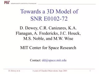
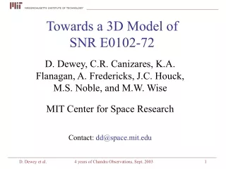
A Coarse 3D Model of E0102-72 Derived from HETG Data. by Dan Dewey MIT Center for Space Research Thanks to "3D & SNR" collegues at MIT: Johns Davis & Houck, Mikes Noble, Nowak &Wise, Claude Canizares, Kathy Flanagan, Amy Fredericks, Glenn Allen, Norbert Schulz, Mike Stage

E N D
A Coarse 3D Model of E0102-72 Derived from HETG Data by Dan Dewey MIT Center for Space Research Thanks to "3D & SNR" collegues at MIT: Johns Davis & Houck, Mikes Noble, Nowak &Wise, Claude Canizares, Kathy Flanagan, Amy Fredericks, Glenn Allen, Norbert Schulz, Mike Stage Contact: dd@space.mit.edu Poster 24.04, AAS HEAD Meeting, 2004
HETG Analysis of E0102 Ne X • Analysis of the Ne X dispersed images suggests regions of red and blue shift appearing on the sky as displaced rings. • Red: 900 and 1800 km/s • Green: -900 km/s • Blue: -1800 km/s • See Flanagan et al. 2004, ApJ • Interpret this as cylinder viewed almost end-on: "True-color" image (above); Ne X line "color-velocity" map: Poster 24.04, AAS HEAD Meeting, 2004
O III Long-slit spectrum "Thanks to You-Hua Chufor thedata! " FP image of E0102 Long slit spectrumin O III, 5007 Å,shows similar spatial-velocity structure tothe Ne X X-ray line. - 1800km/s - 900km/s + 900km/s - + 1800km/s ? But where's the red-shifted emission in the optical flux. Perhaps … see next slide. Poster 24.04, AAS HEAD Meeting, 2004
* An aside… Transmission of gas & dust O VI Perhaps there's equatorial dust absorbing the back-half of the ejecta in the optical? X-ray O III Dust attenuatesthe 5007 Å line butnot X-ray orIR emission. Dust? Spitzer IR bands X-ray and IR black bodies Observer O, Ne, etc. ejecta Blastwave sphere Poster 24.04, AAS HEAD Meeting, 2004
Constructing a 3D Model Analogous to the Ne X resultconstruct cylinders of emissionfrom each ion. From Flanagan et al. 2004the radii of the cylinders varyfrom ion to ion, see Table below. Also include a Blastwavesphere of emission (Hughes 1994)with a vnei spectrum andabundances ~ 0.3 solar. ions Poster 24.04, AAS HEAD Meeting, 2004
Cylindrical Components Poster 24.04, AAS HEAD Meeting, 2004
Encoding the Model Spatial: O VIIemissionmeasurearray: Each component is a3-D array of values,(e.g., 87^3 elements)giving the "norm" ofthe spectral model ineach local cell. Spectral: "Single ion" (or "vnei") spectra are createdat nominal values of T_e and for v=0. local EM Poster 24.04, AAS HEAD Meeting, 2004
"Evaluating" the Model • Assume the source is optically thin: • concatenate component photon/count outputs. • Create "output" photons from each component as a: • random spatial location determined by "norm" array values. • and project to 2-D on sky location. • random spectral wavelength based on • spectrum assigned. • number created determined by spectrum • and optionally an "arf" as well. v ~ r los r • Modify wavelengths using • line-of-sight angle for Doppler: • v ~ r spherical velocity field. Poster 24.04, AAS HEAD Meeting, 2004
Comparing Model and Data • Fold simulated photons through instrument, e.g., with a ray-trace. • [Or: modify simulated counts to approximate the instrument effects.] • Variety of HETGS observation outputs that can be compared, e.g., • MEG minus order • MEG plus order • Zeroth-order image • Zeroth-order spectrum • Adjust "norms" of the components for overall coarse agreementof model to data - do it by hand with human "comparison". • Use automated fitting to do fine adjustment of parameters. Poster 24.04, AAS HEAD Meeting, 2004
Z-o Data and Model Data Comparing the Zeroth-order image and theZeroth-order Spectrum. The real data includesbackground eventsand morespatial complexitythan the simple model. Data Model Model [These images are in detector coord.s. Roughly, North is downand East is to left.] Poster 24.04, AAS HEAD Meeting, 2004
MEG-Dispersed Data and Model Data O VII Ne X MEG -1 MEG +1 Fe needed? Ne X Model O VII MEG -1 MEG +1 Poster 24.04, AAS HEAD Meeting, 2004
…Comments on Dispersed Data-Model * The Model reproduces the coarse structure of the Data. * The velocity Doppler effect (due to the cylindricalion emission and spherical velocity field) shows upin both Data and Model as narrower/crisper minus-order ring images. * Is there a need to add some Fe lines in a ring component?E.g., to add emission between O VIII and Ne IX lines? Poster 24.04, AAS HEAD Meeting, 2004
Model Calculations Given the coarse model,the product (n_e * n_i) foreach ion species isdetermined in 3D space. At right the valuesalong a radial sliceare plotted. In the plot on the nextpage the values n_e(r)and n_i(r) have beenself-consistantly calculated. Blastwave,n_e * n_H Ne IX Ne X O VIII O VII O IX O VI Mg XI Ne VIII Mg XII Mg X Poster 24.04, AAS HEAD Meeting, 2004
Radial Profile of Densities n_e n_H, Blastwave Blastwavedensities ofelements(~0.3 solar) Mg XI O IX O VII O VIII O VI Ne X Ne IX Ne VIII Mg XII Mg X n_O n_Ne n_Mg Poster 24.04, AAS HEAD Meeting, 2004
Calculating Element Masses Using the values of n_ion obtained above,the mass of each element in the model canbe calculated as the sum of masses of theindividual ions, see Table at right. Note that non-X-ray visible ions such asO VI and Ne VIII have been included atlevels with comparable densities to theX-ray visible ions --- compatible with auniform homogeneous ejecta elementdistribution. Poster 24.04, AAS HEAD Meeting, 2004
Further work… [Another aside: Is E0102's morphology/flux changing over the ~3 yearsbetween HETGS obervations ? Due to ionization changes rather than motion ?] • Add spatial complexity to the model, e.g., azimuthal variation Note that the 3D array implementation allows adjusting each of the 3Darray values to create essentially arbitrary emission distributions. • Develop better comparison methods and tools There is a lot of information in the data - on small and large scales. • Compare multiple data sets A single model can be used to output simulated HETGS, XMM/RGS, andAstro-E2/XRS data simulations. Compare each/all of these to their realdata sets and adjust the model appropriately. Poster 24.04, AAS HEAD Meeting, 2004
Hydra: The Bigger Picture The work to create a 3D model of E0102 described above is part of a larger effort we've named "Hydra". The block diagram at right shows the many heads of Hydra - the many components to the full 3D modeling process. The E0102 activies above are used to describe Hydra concepts and goals in thepages at right. (Hydra graphic from: http://www.pantheon.org/areas/gallery/folklore/greek_heroic/hydra.html) Poster 24.04, AAS HEAD Meeting, 2004
Hydra: Block Diagram Poster 24.04, AAS HEAD Meeting, 2004
Hydra: 3D Source Modeling andX-Ray "Rendering" The method of using 3D arrays to specify propertiesof the 3D model described above is just one of manyways to encode 3D information. Other possibilites includeanalytic descriptions with a component algebra. The generation of rays from the model can be viewedas a form of "rendering" and in the extreme it takeson all the complexity of radiation transport. Efficienciesin rendering may be improved by matching the source modelproperties with the method of encoding the problem. Poster 24.04, AAS HEAD Meeting, 2004
Hydra: Comparing Data and Folded Model One issue to explore more is the method to comparemulti-dimensional data sets, e.g., the dispersed imagesfrom "real data" with a forward folded (ray-traced)simulation output. It may be important and useful for human insight toguide the selection and definition of a fit metric fordifferent fitting situations. For example, the ratioof flux (projected) interior to the E0102 ejecta ringcompared with the flux in the limb of the blast wavemay be very sensitive to, say, the blastwave shellthickness. Poster 24.04, AAS HEAD Meeting, 2004
Hydra: Instrument(s) Modeling One goal of the Hydraeffort is to allow andsupport multiple datasets from multipleobservatories. As a simple example,the spectral image andhistogram at left werecreated from the coarse E0102 model and foldedthrough a simple approx-imation of the XMM RGS Grating response. O VIII Ne X O VII The width of the lines is due toboth the spatial and velocitystructure in the 3D model. Poster 24.04, AAS HEAD Meeting, 2004