Download
1 / 28
320 likes | 523 Vues
Introduction to Assembly Chapter 2. The AVR microcontroller and embedded systems using assembly and c. Topics. AVR’s CPU Its architecture Some simple programs Data Memory access Program memory RISC architecture. AVR’s CPU. SREG:. CPU. ALU. R0. R1. R2. …. …. PC. R15. R16.

E N D
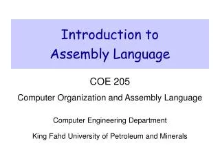
Introduction to AssemblyChapter 2 The AVR microcontroller and embedded systems using assembly and c
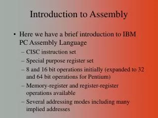
Topics • AVR’s CPU • Its architecture • Some simple programs • Data Memory access • Program memory • RISC architecture
AVR’s CPU SREG: CPU ALU R0 R1 R2 … … PC R15 R16 R17 Instruction decoder Instruction Register registers N H Z I S V C T R30 R31 • AVR’s CPU • ALU • 32 General Purpose registers (R0 to R31) • PC register • Instruction decoder
Some simple instructions1. Loading values into the general purpose registers SREG: CPU ALU R0 R1 R2 … … PC R15 R16 R17 Instruction decoder Instruction Register registers N H Z I S V C T R30 R31 LDI (LoadImmediate) • LDI Rd, k • Its equivalent in high level languages: Rd = k • Example: • LDI R16,53 • R16 = 53 • LDI R19,132 • LDI R23,0x27 • R23 = 0x27
Some simple instructions2. Arithmetic calculation SREG: CPU ALU R0 R1 R2 … … PC R15 R16 R17 Instruction decoder Instruction Register registers N H Z I S V C T R30 R31 • There are some instructions for doing Arithmetic and logic operations; such as: ADD, SUB, MUL, AND, etc. • ADD Rd,Rs • Rd = Rd + Rs • Example: • ADD R25, R9 • R25 = R25 + R9 • ADD R17,R30 • R17 = R17 + R30
A simple program SREG: CPU ALU R0 R1 R2 … … PC R15 R16 R17 Instruction decoder Instruction Register registers N H Z I S V C T R30 R31 • Write a program that calculates 19 + 95 LDI R16, 19 ;R16 = 19 LDI R20, 95 ;R20 = 95 ADD R16, R20 ;R16 = R16 + R20
A simple program • Write a program that calculates 19 + 95 + 5 LDI R16, 19 ;R16 = 19 LDI R20, 95 ;R20 = 95 LDI R21, 5 ;R21 = 5 ADD R16, R20 ;R16 = R16 + R20 ADD R16, R21 ;R16 = R16 + R21 LDI R16, 19 ;R16 = 19 LDI R20, 95 ;R20 = 95 ADD R16, R20 ;R16 = R16 + R20 LDI R20, 5 ;R20 = 5 ADD R16, R20 ;R16 = R16 + R20
Some simple instructions2. Arithmetic calculation SREG: CPU ALU R0 R1 R2 … … PC R15 R16 R17 Instruction decoder Instruction Register registers N H Z I S V C T R30 R31 • SUB Rd,Rs • Rd = Rd - Rs • Example: • SUB R25, R9 • R25 = R25 - R9 • SUB R17,R30 • R17 = R17 - R30
Some simple instructions2. Arithmetic calculation SREG: CPU ALU R0 R1 R2 … … PC R15 R16 R17 Instruction decoder Instruction Register registers N H Z I S V C T R30 R31 • INC Rd • Rd = Rd + 1 • Example: • INC R25 • R25 = R25 + 1 • DEC Rd • Rd = Rd - 1 • Example: • DEC R23 • R23 = R23 - 1
Data Address Space LDS (Load direct from data space) LDS Rd, addr ;Rd = [addr] Example: Write a program that stores 55 into location 0x80 of RAM. Example: LDS R1, 0x60 STS (Store direct to data space) Example: What does the following instruction do? LDS R20,2 Example: Write a program that copies the contents of location 0x80 of RAM into location 0x81. Example: Store 0x53 into the SPH register. The address of SPH is 0x5E STS addr,Rd ;[addr]=Rd Example: Add contents of location 0x90 to contents of location 0x95 and store the result in location 0x313. Example: STS 0x60,R15 ; [0x60] = R15 Solution: LDS R20, 0x90 ;R20 = [0x90] LDS R21, 0x95 ;R21 = [0x95] ADD R20, R21 ;R20 = R20 + R21 STS 0x313, R20 ;[0x313] = R20 Solution: LDI R20, 0x53 ;R20 = 0x53 STS 0x5E, R20 ;SPH = R20 Solution: LDI R20, 55 ;R20 = 55 STS 0x80, R20 ;[0x80] = R20 = 55 Answer: It copies the contents of R2 into R20; as 2 is the address of R2. Solution: LDS R20, 0x80 ;R20 = [0x80] STS 0x81, R20 ;[0x81] = R20 = [0x80]
Data Address Space IN (IN from IO location) IN Rd,IOaddress ;Rd = [addr] Example: IN R1, 0x3F ;R1 = SREG IN R17,0x3E ;R17 = SPH OUT (OUT to IO location) Using Names of IO registers Example: Write a program that adds the contents of the PINC IO register to the contents of PIND and stores the result in location 0x90 of the SRAM OUT IOAddr,Rd ;[addr]=Rd Example: OUT SPH,R12 ;OUT 0x3E,R12 IN R15,SREG ;IN R15,0x3F Example: OUT 0x3F,R12 ;SREG = R12 OUT 0x3E,R15 ;SPH = R15 Solution: IN R20,PINC ;R20 = PINC IN R21,PIND ;R21 = PIND ADD R20,R21 ;R20 = R20 + R21 STS 0x90,R20 ;[0x90] = R20
Status Register (SREG) N H Z S V C I T SREG: CPU ALU Solution: $9C 1001 1100 - $9C 1001 1100 $00 0000 0000 R20 = $00 C = 0 because R21 is not bigger than R20 and there is no borrow from D8 bit. Z = 1 because the R20 is zero after the subtraction. H = 0 because there is no borrow from D4 to D3. Solution: 1 $38 0011 1000 + $2F 0010 1111 $67 0110 0111 R16 = 0x67 C = 0 because there is no carry beyond the D7 bit. H = 1 because there is a carry from the D3 to the D4 bit. Z = 0 because the R16 (the result) has a value other than 0 after the addition. Solution: $52 0101 0010 - $73 0111 0011 $DF 1101 1111 R20 = $DF C = 1 because R21 is bigger than R20 and there is a borrow from D8 bit. Z = 0 because the R20 has a value other than zero after the subtraction. H = 1 because there is a borrow from D4 to D3. Solution: $A5 1010 0101 - $23 0010 0011 $82 1000 0010 R20 = $82 C = 0 because R21 is not bigger than R20 and there is no borrow from D8 bit. Z = 0 because the R20 has a value other than 0 after the subtraction. H = 0 because there is no borrow from D4 to D3. Solution: 1 $9C 1001 1100 + $64 0110 0100 $100 1 0000 0000 R20 = 00 C = 1 because there is a carry beyond the D7 bit. H = 1 because there is a carry from the D3 to the D4 bit. Z = 1 because the R20 (the result) has a value 0 in it after the addition. R0 R1 R2 … … PC R15 R16 Instruction decoder R17 Instruction Register registers N H Z I S V C T R30 R31 Example: Show the status of the C, H, and Z flags after the addition of 0x38 and 0x2F in the following instructions: LDI R16, 0x38 ;R16 = 0x38 LDI R17, 0x2F ;R17 = 0x2F ADD R16, R17 ;add R17 to R16 Example: Show the status of the C, H, and Z flags after the addition of 0x9C and 0x64 in the following instructions: LDI R20, 0x9C LDI R21, 0x64 ADD R20, R21 ;add R21 to R20 Example: Show the status of the C, H, and Z flags after the subtraction of 0x23 from 0xA5 in the following instructions: LDI R20, 0xA5 LDI R21, 0x23 SUB R20, R21 ;subtract R21 from R20 Example: Show the status of the C, H, and Z flags after the subtraction of 0x73 from 0x52 in the following instructions: LDI R20, 0x52 LDI R21, 0x73 SUB R20, R21 ;subtract R21 from R20 Example: Show the status of the C, H, and Z flags after the subtraction of 0x9C from 0x9C in the following instructions: LDI R20, 0x9C LDI R21, 0x9C SUB R20, R21 ;subtract R21 from R20 SREG: Carry Interrupt Zero oVerflow Temporary Negative Sign N+V Half carry
Assembler Directives.EQU and .SET • .EQU name = value • Example: .EQU COUNT = 0x25 LDI R21, COUNT ;R21 = 0x25 LDI R22, COUNT + 3 ;R22 = 0x28 • .SET name = value • Example: .SET COUNT = 0x25 LDI R21, COUNT ;R21 = 0x25 LDI R22, COUNT + 3 ;R22 = 0x28 .SET COUNT = 0x19 LDI R21, COUNT ;R21 = 0x19
Assembler Directives.INCLUDE M32def.inc .equ SREG = 0x3f .equ SPL = 0x3d .equ SPH = 0x3e .... .equ INT_VECTORS_SIZE = 42 ; size in words Program.asm .INCLUDE “M32DEF.INC” LDI R20, 10 OUT SPL, R20 • .INCLUDE “filename.ext”
Assembler Directives.ORG 00 E205 01 0000 02 0000 03 0000 04 0000 05 0000 06 0000 07 E314 08 E321 09 0000 0A 0000 Program.asm .ORG 0 LDI R16, 0x25 .ORG 0x7 LDI R17, 0x34 LDI R18, 0x31 • .ORG address assembler
Assembler Assembly assembler Machine Language
Flash memory and PC register 00 E205 01 E314 02 E321 03 0F01 04 0F02 05 E01B 06 0F01 07 9300 08 0300 09 940C 0A 0009 LDI R16, 0x25 LDI R17, $34 LDI R18, 0x31 ADD R16, R17 ADD R16, R18 LDI R17, 11 ADD R16, R17 STS SUM, R16 HERE:JMP HERE E205 E314 E321 0F01 0F02 16-bit E01B 0F01 9300 0300 940C 0009 3 0 9 1 5 2 7 A 4 8 B 6
Fetch and execute 00 E205 01 E314 02 E321 03 0F01 04 0F02 05 E01B 06 0F01 07 9300 08 0300 09 940C 0A 0009 • Old Architectures Instruct 4 Instruct 3 Instruct 2 16-bit Instruct 1 Fetch Execute
Pipelining 00 E205 01 E314 02 E321 03 0F01 04 0F02 05 E01B 06 0F01 07 9300 08 0300 09 940C 0A 0009 • Pipelining Instruct 4 Instruct 3 Instruct 2 16-bit Instruct 1 Fetch Execute
How to speed up the CPU • Increase the clock frequency • More frequency More power consumption & more heat • Limitations • Change the architecture • Pipelining • RISC
Changing the architectureRISC vs. CISC • CISC (Complex Instruction Set Computer) • Put as many instruction as you can into the CPU • RISC (Reduced Instruction Set Computer) • Reduce the number of instructions, and use your facilities in a more proper way.
RISC architecture • Feature 1 • RISC processors have a fixed instruction size. It makes the task of instruction decoder easier. • In AVR the instructions are 2 or 4 bytes. • In CISC processors instructions have different lengths • E.g. in 8051 • CLR C ; a 1-byte instruction • ADD A, #20H ; a 2-byte instruction • LJMP HERE ; a 3-byte instruction
RISC architecture • Feature 2: reduce the number of instructions • Pros: Reduces the number of used transistors • Cons: • Can make the assembly programming more difficult • Can lead to using more memory
RISC architecture • Feature 3: limit the addressing mode • Advantage • hardwiring • Disadvantage • Can make the assembly programming more difficult
RISC architecture • Feature 4: Load/Store • LDS R20, 0x200 • LDS R21, 0x220 • ADD R20, R21 • STS 0x230, R20
RISC architecture Fetch Execute • Feature 5 (Harvard architecture): separate buses for opcodes and operands • Advantage: opcodes and operands can go in and out of the CPU together. • Disadvantage: leads to more cost in general purpose computers. LDS R20, 0x100 ; R20 = [0x100] ADD R20,R21 ; R20 = R20 + R21 ADD R20, R21 LDS R20, 0x100 CPU Control bus Control bus Code Memory Data Memory Data bus Data bus Address bus Address bus
RISC architecture • Feature 6: more than 95% of instructions are executed in 1 machine cycle
RISC architecture • Feature 7 • RISC processors have at least 32 registers. Decreases the need for stack and memory usages. • In AVR there are 32 general purpose registers (R0 to R31)