Download
1 / 17
170 likes | 173 Vues
This article discusses a distributed simulation architecture for the design of cooperative Advanced Driver Assistance Systems (ADAS) that improve road safety in degraded conditions. It covers the DIVAS project, which focuses on integrating information from infrastructure and vehicles to provide drivers with an integrated index for self-safety. The project includes processing weather conditions from infrastructure and in-vehicle sensors, merging information for a coherent view on visibility conditions, and defining safe speed profiles for foggy conditions.

E N D
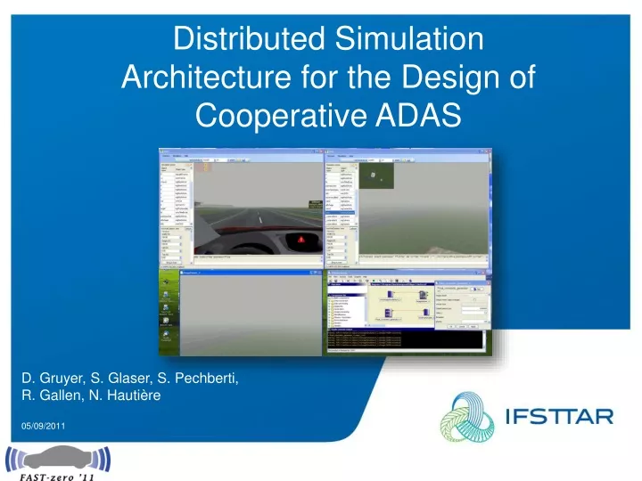
Distributed Simulation Architecture for the Design of Cooperative ADAS D. Gruyer, S. Glaser, S. Pechberti, R. Gallen, N. Hautière 05/09/2011
Introduction • Road safety: an actual and important issue • Need of safety applications to properly react • to close and unexpected events in degraded • Conditions: • collision avoidance, • lane departure avoidance. • Dedicated to degraded weather conditions • (rain, fog …): • low capacity to anticipate events • bad human perception • bad interpretation • inappropriate decision and reaction
Context • DIVAS project: dialog between Infrastructure and Vehicles • Improve road safety. • Provide to the driver an integrated index for self safety from: • Road surface state • Current weather condition • Road surface geometry The DIVAS project has developed the full system and has studied the different consequences technological and sociological aspect
DIVAS project: infrastructure • Processing of the weather condition from infrastructure In fog condition, the amount of energy that is lost along the way is described by the optical density k (extinction coefficient). The effect of light scattering in the presence of fog is to modify the transmissivity T by an overall reduction of contrasts as a function of distance. In order to assess the visibility distance, 2 sensors may be used on the infrastructure: Road Visibilitymeters: quantifying the light scattered within a sufficiently wide and well-defined solid angle. Road-Side Camera: estimating the apparent luminance of the road surface L given by Koschmieder's law.
DIVAS project: infrastructure • Processing of the weather condition from road side camera Three steps are processed: • Computation of a background model of the scene to filter all moving objects on the road surface • Manual rough segmentation of the road area to reduce the search area • Adaptive region growing in the background model restricted to the manually segmented area Having the road surface, measuring the median intensity on each line of the area of interest allows to obtain I (intensity of a pixel) and then compute its inflection point vi.
DIVAS project: vehicle • Processing of embedded sensors and vehicle control Fog detection and characterization by in-vehicle camera same than in the road-side system But the camera is moving, No computation of the background model, no manual segmentation of the road surface, the expected accuracy of camera sensors is not so good than the road-side camera,
DIVAS project: merging information • Merging of information from infrastructure and vehicles The roadside camera processing algorithms is the main RSU environmental sensor, Data coming from passing vehicles (wipers status, fog light status…) are complementary. In order to give a coherent view on the visibility conditions in the area of the RSU Merge the different data sources The visibility range is then the spatial barycenter of the different sensors outputs. The corresponding uncertainty of the measurements is the sum of: • The uncertainty of the sensors themselves. • The uncertainty coming from the distance to the data sources. • The uncertainty coming from the status of fog lamps of the vehicles on the road section. Goal: Data Aggregation in the vehicle for Advisory Speed Determination
Speed profile adaptationin foggy condition • Definition of a safe speed Event appearing obstacle at a visibility distance After a given reaction time Tr, the driver brakes with a strong deceleration The stopping distance, Dstop could be expressed as: But foggy condition is often associated with a wet road decreased road friction: During a strong braking, the mobilized friction increases in time. It is a conservative hypothesis to consider the deceleration as a constant, below the maximal possible deceleration. The maximal speed is then:
Speed profile adaptationin foggy condition • Safe speed results from detected visibility distance
Speed profile adaptationin foggy condition • Definition of a safe speed profile In order to define a safe speed profile to reach the speed, several parameters must be used describing : • the road surface, • the vehicle dynamic and • the driver behavior. The process is modified in order to take into account the visibility distance and the associated speed. The limit condition is computed from both visibility distance condition (Vvis in previous slide) and the safe dynamic condition: : road curvature, : road slope, : bank angle, lat and lon : desired mobilized friction. H: vehicle center of gravity height, Lf : distance from the front axle.
Speed profile adaptationin foggy condition • Combined Safe speed and visibility speed
SiVIC: a simulator for Vehicle, Infrastructure and sensors modeling • Sensors simulator for ADAS prototyping
I / O C o n n e c t o r s Data Acquisition Software in the loop Hardware in the loop Control/Command SiVIC platform: constraints • Can run in real time, in virtual time or off line • Environments complexity • Traffic management • Number of vehicles • Complexity of the vehicle models (in fct of the application type) • Real time access to the objects and environment attributes • Stiffness, viscosity, torques, braking ... • Object position, rotation • Light parameters • Sensors attributes • … • Add and delete objects during the simulation • Vehicles • Sensors • Obstacles • Climate and weather conditions • … • Events management (type of event, type of object, time, variables) • 2 types of modules: a simulation engine • a set of plug-ins Spatio-temporalsensors raw data
« multi-renderer » approach : plug-ins of rendering adapted to sensors • Filters for optimised renderer post processing • Filter for noises management • Filter for fog generation • Filter for the optical deformation • Filter for the rain drop (on the camera objective) • Filter for the Depth of Field • Filter for the colours management • Auto Exposition • Auto Focus • … • HDR rendering • Use of HDR texture (High Dynamic Range) • Generation of HDR image (16 and 32 bits) • Meta materials • Modelling of the Radar (RCS) • Modelling of the cameras (BRDF) Initial rendering Rendering + Filter 1 Rendering+ Filter 1 + Filter2 Rendering+ Filter 1 + Filter2 + … + Filter n View.AddFiltrer filtername
SiVIC: A distributed architecture • Need to share the processing for DIVAS project • DDS (Distributed Data Storage) bus allows to share processing either on several computers or in several applications
Application of SiVIC in DIVAS context • First SiVIC dedicated to infrastructure processing • Second SiVIC dedicated to embedded processing
Conclusion and perspective • Virtual platform allowing every stages needed for the design of cooperative (V2V, V2I) applications (sensors simulation, perception algorithm development, data and information communication, vehicle control and automation). • Distributed virtual architecture for sensors, vehicle and infrastructure • Interconnection of virtual platform with prototyping platform (RTMaps, Matlab, ...). • Several virtual ground truth sensors are also available in order to qualify and to quantify the quality of the application. • Application based on DIVAS project: visibility distance estimation, speed profile adaptation. • Next step: interaction between real and virtual environment. • Next step: communication simulation implemented in SiVIC. • This work is part of 2 French research projects: DIVAS (ANR) and eMotive (FUI).