Download

1 / 34
1.5k likes | 2.95k Vues
PROTECTIVE RELAYS. By: KEERTHIRAJ B L KOUSHIK K. WHAT IS PROTECTIVE RELAY *.

E N D
PROTECTIVE RELAYS By: KEERTHIRAJ B L KOUSHIK K
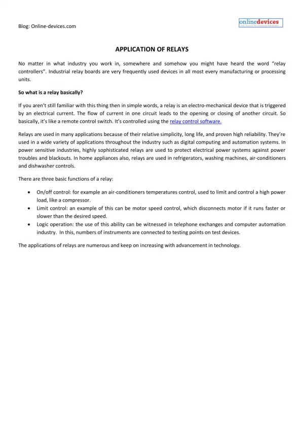
WHAT IS PROTECTIVE RELAY* In electrical engineering, a protective relay is a relay device designed to trip a circuit breaker, when a fault is detected. The first protective relays were electromagnetic devices, relying on coils operating on moving parts to provide detection of abnormal operating conditions such as over-current, over-voltage, reverse power flow, over-frequency, and under-frequency.
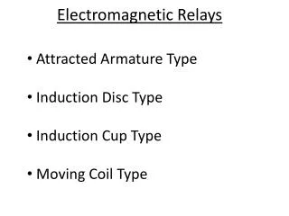
Electromagnetic • attraction type relay* Electromagnetic attraction relays operate by virtue of an armature being attracted to the poles of an electromagnet or a plunger being drawn into a solenoid. Such relays may be actuated by DC or AC quantities Index:
BALANCED BEAM TYPE RELAY* This type of balanced beam relay has a fixed beam and an electromagnet (EM) as shown in the figure. The EM has two windings, one is energized by the voltage and the other energized by the current. Under normal conditions, the pull due to the voltage (restraint quantity) will be high and hence the contact remains open. When a fault occurs, the current increases, the pull due to current will be more than the pull due to voltage. This closes the contacts of the trip circuit. This balanced beam type relay consists of a horizontal beam pivoted centrally, with one armature attached to either side. There are two coils, one on each side. The beam remains horizontal till the operating force becomes greater than the restraining force. Current in coil gives the operating force and in the other, the restraining force. When the operating force or torque increases, the beam tilts and then the contact closes. The relay then actuates the tripping mechanism of the circuit breaker controlling the line / equipment. Working:
BALANCED BEAM TYPE RELAY: Under normal condition: To trip circuit V I From CT From PT
BALANCED BEAM TYPE RELAY: Under abnormal condition: To trip circuit V I From CT From PT Index:
Induction type relay* An Induction Type Relay is a split-phase induction motor with contacts. Actuating force is developed in a movable element that may be a disc or other form of rotor of non-magnetic current-conducting material by the interaction of electromagnetic fluxes with eddy currents that are induced in the rotor by these fluxes.
COIL RATING: Index:
INDUCTION DISC TYPE RELAY* • It has a metallic disc free to rotate between the poles of two electro magnets. • The spindle of this disc carries a moving contact which bridges two fixed contacts when the disc rotates through an angle, which is adjustable between 0o to 360o. By adjusting this angle the travel of moving contact can be adjusted so that the relay can be given any desired time setting which is indicated by a pointer. The dial is calibrated from 0-1. The relay time from name plate cure is to be multiplied by time multiplier setting.
The upper magnet has two windings. The primary coil is connected to the secondary of CT through tapping's in it. These tapping's are connected to plug Settings Bridge. The secondary is connected to the lower electro magnet. The torque exerted on the disc is due to the interaction of eddy current produced therein by the flux from the upper EM and the lower EM. The relay setting is 50% to 200% in steps of 25%. Working:
INDUCTION DISC TYPE RELAY: Video: Index:
DIRECTION TYPE RELAYS* A directional relay is a protective relay used in power system protection. It is used to signal whether the power flow it is sensing is in the direction as set by the user. This could be useful to have protective function to execute or not depending on the direction of the power flow. Index:
REVERSE CURRENT TYPE RELAY* This relay is used as part of voltage regulator and you can see it in the Picture 1. The reverse current relay is in most cases incorporated in three-unit regulator together with voltage regulator and current limiter. The purpose is to prevent current from battery and feeding the generator. The relay consists of two coils on one core and spring-controlled armature. There are two coils: one for voltage which is in parallel with generator and another one for current in series with generator. Apparently, the voltage coil is energized when generator reaches operational voltage.
When generator starts, operating voltage is rising up, and first winding (voltage winding) will cause sufficient magnetism and then close the contacts of relay. So, in this situation we have turn on generator on aircraft busbar, and we also have battery charging because generator is connected to the battery too. However, in malfunction situation, when output voltage of generator is below value of battery voltage, we have current discharging from battery. Obviously, reverse current situation occurs. Evidently, current now flows in opposite direction, and it is energizing the current winding, relay is switched off and we turn off the generator from electrical distribution. Working:
REVERSE CURRENT TYPE RELAY: Index:
RELAYS based on timing* Their purpose is to control an event based on time. The difference between relays and time delay relays is when the output contacts open & close: on a control relay, it happens when voltage is applied and removed from the coil; on time delay relays, the contacts can open or close before or after some time delay. Index:
INSTANTANEOUS TYPE RELAY* • Operates in a definite time when current exceeds its Pick-up value. • Its operation criterion is only current magnitude (without time delay). • Operating time is constant. • There is no intentional time delay.
Coordination of definite-current relays is based on the fact that the fault current varies with the position of the fault because of the difference in the impedance between the fault and the source • The relay located furthest from the source operate for a low current value • The operating currents are progressively increased for the other relays when moving towards the source. • It operates in 0.1s or less Index:
DISTANCE TYPE REALY* There is one type of relay which functions depending upon the distance of fault in the line. More specifically, the relay operates depending upon the impedance between the point of fault and the point where relay is installed. These relays are known as distance relay or impedance relay. Index:
IMPEDENCE TYPE RELAY* The relay whose working depends on the distance between the impedance of the faulty section and the position on which relay installed is known as the impedance relay or distance relay. It is a voltage controlled equipment. The relay measures the impedance of the faulty point, if the impedance is less than the impedance of the relay setting, it gives the tripping command to the circuit breaker for closing their contacts. The impedance relay continuously monitors the line current and voltage flows through the CT and PT respectively. If the ratio of voltage and current is less than the relay starts operating then the relay starts operating.
IMPEDENCE TYPE RELAY: Index:
DIFFERENTIAL TYPE REALY* A differential relay is defined as the relay that operates when the phase difference of two or more identical electrical quantities exceeds a predetermined amount. The differential relay works on the principle of comparison between the phase angle and magnitude of two or more similar electrical quantities. Comparing two electrical quantities in a circuit using differential relays is simple in application and positive in action Index:
CURRENT DIFFERENTIAL RELAY* A relay which senses and operates the phase difference between the current entering into the electrical system and the current leaving the electrical system is called a current differential relay. An arrangement of overcurrent relay connected to operate as a differential relay is shown in the figure below
The arrangement of the overcurrent relay is shown in the figure below. The dotted line shows the section which is used to be protected. The current transformer is placed at both the ends of the protection zone. The secondary of the transformers is connected in series with the help of the pilot wire. Thereby, the current induces in the CTs flows in the same direction. The operating coil of the relay is connected on the secondary of the CTs.
In the normal operating condition, the magnitude of current in the secondary of the CTs remains same. The zero current flows through the operating coil. On the occurrence of the fault, the magnitude of the current on the secondary of CTs becomes unequal because of which the relay starts operating. Index:
OTHER TYPES REALY: Under voltage, current, power relay Over voltage, current, power relay Thermal Relay Rectifier Relay Permanent Magnet Moving Coil Relay Static Relay Gas Operated Relay Index:
THERMAL RELAY* Thermal overload relays are economic electromechanical protection devices for the main circuit. They offer reliable protection for motors in the event of overload or phase failure. The thermal overload relay can make up a compact starting solution together with contactors
LR2-D thermal relay • Fundamental parameter of the main circuit • (a). Rated insulation voltage 660V. • (b). Rated working current 25,36,93A separately. • (c). The regulator seal of rated setting current and setting. • (d). Current of the Thermal component (see list 1) • Auxiliary Circuit • (a). There is one pair of NO/ and N/C contact with electric insulation. • (b). Rated insulation Voltage 500V. • (c). Rated frequency 50-60Hz. • (d). Use group, rated working voltage, appoint thermal current and rated current Index:
RECTIFIER RELAY* Rectifier-Relay. POWER-GATE solid state rectifier-relays are designed to behave like an ideal diode, allowing current to flow in a unidirectional fashion from Source to Load when a trigger signal is applied via the provided control harness.
PVAZ172N Features • 500mΩOn-Resistance • Bounce-free Operation • 1.0 Amp capacity • 4000 V RMS I/O isolation • Solid-State reliability • UL recognition and CSA certification pending Index:
PERMANENT MAGNET MOVING COIL RELAY* The instruments which use the permanent magnet for creating the stationary magnetic field between which the coil moves is known as the permanent magnet moving coil or PMMC instrument. It operates on the principle that the torque is exerted on the moving coil placed in the field of the permanent magnet Index:
GAS OPERATED RELAY* Operation of a Transformer Gas Relay. A typical transformer gas relay consists of two chambers, each performing a distinctive function. ... A float located in this partially oil-filled chamber moves as the gas volume increases. It operates an alarm switch when the amount of gas collected reaches a specified level. Index: