Download
1 / 2
50 likes | 248 Vues
Continuous Incremental Dynamic Recrystallization Mechanism Promotes Cracking in Solder Joints (3-D X-ray Diffraction) Thomas R. Bieler, Michigan State University, DMR 1006656. Subsurface 3-D X-ray. subgrain Rx G Bdy. Rx. Rx.

E N D
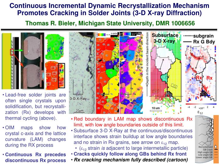
Continuous Incremental Dynamic Recrystallization Mechanism Promotes Cracking in Solder Joints (3-D X-ray Diffraction)Thomas R. Bieler, Michigan State University, DMR 1006656 Subsurface 3-D X-ray subgrain Rx G Bdy Rx Rx • Lead-free solder joints are often single crystals upon solidification, but recrystalli-zation (Rx) develops with thermal cycling (above). • OIM maps show how crystal c-axis and the lattice curvature (LAM) changes during the RX process • Continuous Rx precedes discontinuous Rx process • Red boundary in LAM map shows discontinuous Rx limit, with low angle boundaries outside of this limit. • Subsurface 3-D X-Ray at the continuous/discontinuous interface shows strain buildup at low angle boundaries and no strain in Rx grains, see arrow on 12 map. • (12 strain is adjacent to large intermetallic particle) • Cracks quickly follow along GBs behind Rx front • Rx cracking mechanism fully described (cartoon)
To predict Rx cracking with simulations, slip behavior is needed, and being installed into constitutive modelsThomas R. Bieler, Michigan State University, DMR 1006656 Crystal plasticity finite element models are under development to simulate heterogeneous deformation in solder joints. Many joints consist of three crystal orientations, often in a beach ball geometry with 60 misorientations 2 (like an orange with 6 sections, but with an arbitrary rotation axis orientation) 1 3 Using EBSP data, left simulation shows how preferential shear qualitatively matches what took place in a corresponding experiment; dark blue orientation shears more easily than others. Right simulations show a simplified tri-crystal geometry where the critical resolved shear stress to operate different slip systems were varied based on prior experiments; the bottom example shows an intragranular shear band similar to that observed in experimental samples (red arrows). With good material constitutive models, it will be possible to examine how heterogeneous strain develops, to identify worst case scenarios, and to provide driving force information for recrystallization models that will provide better reliability predictions for electronic systems. 12