Download
1 / 55
550 likes | 553 Vues
Explore the use of lightning observations in understanding thunderstorms, rainfall patterns, and their associated impacts. Learn about the application of these insights in aviation, numerical models, and storm tracking. Discover how lightning mapping complements radar information and provides continuous observations for improved storm detection.

E N D
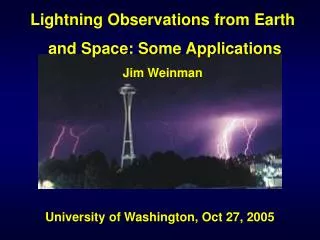
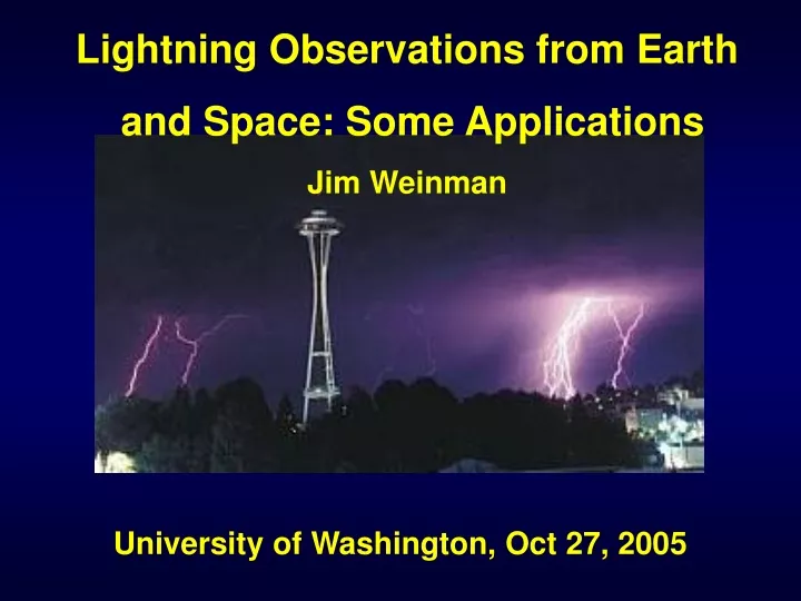
Lightning Observations from Earth and Space: Some Applications Jim Weinman University of Washington, Oct 27, 2005
Example of “TRMM” Merged Microwave-IR 3 Hour Rain Product • This display on http://trmm.gsfc.nasa.gov runs ~ 10 hrs behind real time. • Files are available via ftp://aeolus.nascom.nasa.gov/pub/merged . within ~ 5 hrs. • We need more frequent observations!
Global Convection Diagnostic (GCD) : A Possible Thunderstorm Interpolator(% Fred Mosher) Tir = Twv Tir >Twv • For deep convective clouds, updraft brings cloud particles and water vapor to top of cloud. (IR and Water Vapor temperature are the same) • Clouds drifting away from lift will allow cloud particles to fall. Water Vapor will remain at original level.(IR and WV temperatures will be different)
Comparison of GCD and Lightning Distributions GCD Lightning • Variable consistency, but both are continuous measurements. • GCD responds to vertical motion at the very top of clouds. • Lightning depends on vertical motion deeper within clouds.
OBJECTIVES • Understand horizontal & vertical structure of rainfall, its macro- & micro-physical nature, & its associated latent heating • Train & calibrate retrieval algorithms for constellation radiometers • OBJECTIVES • Provide sufficient global sampling to significantly reduce uncertainties in short-term rainfall accumulations • Extend scientific and societal applications GPM Reference Concept Core Constellation • Core Satellite • Non-sun-synchronous orbit • ~ 65° inclination • ~400 km altitude • Dual frequency radar (NASDA) • Ku-Ka Bands (13.6-35 GHz) • ~ 4 km horizontal resolution • ~250 m vertical resolution • Multifrequency radiometer (NASA) • 10.7, 19, 22, 37, 85, (150/183 ) GHz V&H • TRMM-like spacecraft (NASA) • Constellation Satellites • 3-hour goal at ~90% of time • Revisit time • Sun-synch & non-sun- synch orbits • Pre-existing operational-experimental & dedicated satellites with PMW radiometers • 600-900 km altitudes
Mean Diurnal Rainfall and Lightning Cycles CaPE Days 189-231 Mean Rainfall (mm) Mean C-G Flash Rate Hour (UTC) • Current observation frequency may miss significant convective events. • The situation has improved with addition of AQUA and 3 NOAA satellite with microwave sounders.
Motivations for Lightning Mapping • Better determination of thunderstorm location and intensity in regions of poor radar coverage. • Complements the storm information from radar. • Only technically feasible technology for oceanic and global coverage. • Permits continuous observations. • Aviation (safety and routing) • Initialization of Numerical Models (places storms in right places; redistributes energy ) • Lightning detection is cheap.
SomeRelationshipsin Model & Observations Graupel mass From Ziegler et al. (2003) Lightning Lightning rates are proportional to graupel mass, to graupel volume, to cloud ice, and to updraft mass flux through the –10 C level
Compendium of LIS Flash Density vs IWC between 7-9 km (1998-2000) IWC (g/m2)
Evolution of storm growth and electrification. • Total lightning (top panel) follows the precipitation (middle panel) and updraft (bottom panel) as storm grows and decays. • C-C lightning starts a bit sooner and is more abundant than C-G • [After Goodman et al., 1988; Kingsmill and Wakimoto, 1991].
Lightning Correlations with Radar-Inferred Storm Properties Consistently highest correlations with • Hail Probability or Severe Hail Probability or Hail Diameter • Area with 45 dBZ ( from MacGorman) Also for maritime lightning?
Empirical Rain Rate as a Function of Sferics Rate Probability matched rain r rate, Ri(Fi) (mm/h) ,from m microwave retrieval vs r sferics rate / 15 min . ∫Ri0 (R) dR = ∫Fi0 (F) dF Technique does not r require exact pixel- by- xel exact pixel- by- pixel co-registration. ( (Zawadski & Claheiros)
Lightning vs Convective Rain Rate from TRMM Microwave Imager + Sferics and from Solomon & Baker Model (1998) Rainfall Rate (mm/h) Rainfall Rate (mm/h) Flash Rate (min-1) Flash Rate (min-1) Rainfall Rate (mm/h) Rain rate vs Flash Rate from Solomon & Baker, (1998). The smooth curve is an extrapolation of fitted curve from measurements on left. TMI convective rain over 0.6ox0.6o box vs sferics rate within 15 min of overpass. Smooth curve was obtained from histogram matching
Designation Frequency Wavelength ELF extremely low frequency 3Hz to 30Hz 100'000km to 10'000 km SLF superlow frequency 30Hz to 300Hz 10'000km to 1'000km ULF ultralow frequency 300Hz to 3000Hz 1'000km to 100km VLF very low frequency 3kHz to 30kHz 100km to 10km LF low frequency 30kHz to 300kHz 10km to 1km MF medium frequency 300kHz to 3000kHz 1km to 100m HF high frequency 3MHz to 30MHz 100m to 10m VHF very high frequency 30MHz to 300MHz 10m to 1m UHF ultrahigh frequency 300MHz to 3000MHz 1m to 10cm MW microwaves 3GHz to 100GHz 10cm to 3 mm MmW millimneter wave 100GHz to 500GHz 3 mm to 0.6mm Electromagnetic Spectrum Terminology
VHF Lightning Mapping Station 3-dimensional lightning structure in MCSs VHF Signal Antenna Communication Antennas Electronics Building Site north of Chickasha, Oklahoma
VHF lightning mappers detect pulses of radiation produced by the electrical breakdown processes of lightning in a 5 MHz band within a subset of the VHF (50-120 MHz) band • VHF pulses of radiation are then used to reconstruct the path (map) of CG and Cloud lightning discharges in 2D or 3-Dimensional Mapping within Network Perimeter • 100-200 meter location accuracy • Greater than 95% expected flash detection efficiency • Reduces to 2-Dimensional Mapping well outside of the Network (~150 km) • 2 km or better location accuracy • Greater than 90% expected flash detection efficiency out to 120 km
Schematic view of LDAR 3-D lightning imaging from 7 stations + central processor
Area covered by WSR-88D Reflectivity, LDAR II Total Lightning and CG Lightning Fort Worth WSR-88D Radar Base Reflectivity Image 13 October 2001 at 0105 UTC DFW LDAR II Sources (red) and NLDN CG Flashes (black) detected between 0103-08 UTC 13 October 2001 from N. W. S. Demetriades, Ronald L. Holle and Martin J. Murphy (2004)
Plan position indicator comparable to radar (PPI). Side views show c-g and c-c lightning. Probability distributions are shown in the upper right. (from P. Krehbiel et al. 2002) Example of LDAR data
Designation Frequency Wavelength ELF extremely low frequency 3Hz to 30Hz 100'000km to 10'000 km SLF superlow frequency 30Hz to 300Hz 10'000km to 1'000km ULF ultralow frequency 300Hz to 3000Hz 1'000km to 100km VLF very low frequency 3kHz to 30kHz 100km to 10km LF low frequency 30kHz to 300kHz 10km to 1km MF medium frequency 300kHz to 3000kHz 1km to 100m HF high frequency 3MHz to 30MHz 100m to 10m VHF very high frequency 30MHz to 300MHz 10m to 1m UHF ultrahigh frequency 300MHz to 3000MHz 1m to 10cm MW microwaves 3GHz to 100GHz 10cm to 3 mm MmW millimneter wave 100GHz to 500GHz 3 mm to 0.6mm Electromagnetic Spectrum Terminology
VLF Sferics Detection Networks • UKMO ( Europe etc., Tony Lee et al.) • STARNET ( Eastern US and Atlantic, NASA GSFC) • WWLLN ( Global, NZ & UW) • Zeus ( Europe and Africa, Athens Observatory, STARNET- II) • PACNET ( Pacific, Hawaii, Steve Businger) • Los Alamos Nat’l. Lab. ( US )
Components of the STARNET Digital Receiver Cheap accurate timing Hi speed Internet Fast signal processing
Determination of Arrival Time Difference (ATD) We know neither the location of the event nor when it occurred. We can only measure the ATD at pairs of receivers. That is an art form. Pulse shape at a range of 6,000 Km Pulse shape at a range of 15,000 Km Correlation Δt
Arrival Time Differences Measured by Various Pairs of Five Receivers Actual Flash Note that slight errors in measuring ATD can produce streaks
Red circles identify operating receivers.(25 and more to come) Data collected over 40 min. Sizes of dots diminish in 10 min intervals WWLLN: World-Wide Long-range Lightning NetworkP.I.sDick Dowden & Bob Holzworth<http://webflash.ess.washington.edu>
An Example of WWLLN Sferics Observations Superimposed on IR Imagery from Geostationary Satellites.
Lightning Production • To produce lightning, a storm’s updraft speed usually must be large enough to loft graupel in the mixed phase region. (> 6-7 m s-1) • Graupel also scatters microwave radiation that is measured by passive radiometers on operational satellites.
Two-Hourly Distribution of Lightning in 1998 Ground-hog day Super-storm (1400 UTC, Feb. 2 - 1200 UTC Feb. 3, 1998) Loop current trigger Post-frontal convection, Cloud Dynamics, Houze (1993) p .472 Power outage in Miami
Sferics Distribution on Dec. 24 1999 After Before
NCEP Reanalysis of Xmas eve 1999 StormNote 960 mb minimum surface pressure
Designation Frequency Wavelength ELF extremely low frequency 3Hz to 30Hz 100'000km to 10'000 km SLF superlow frequency 30Hz to 300Hz 10'000km to 1'000km ULF ultralow frequency 300Hz to 3000Hz 1'000km to 100km VLF very low frequency 3kHz to 30kHz 100km to 10km LF low frequency 30kHz to 300kHz 10km to 1km MF medium frequency 300kHz to 3000kHz 1km to 100m HF high frequency 3MHz to 30MHz 100m to 10m VHF very high frequency 30MHz to 300MHz 10m to 1m UHF ultrahigh frequency 300MHz to 3000MHz 1m to 10cm MW microwaves 3GHz to 100GHz 10cm to 3 mm MmW millimneter wave 100GHz to 500GHz 3 mm to 0.6mm Electromagnetic Spectrum Terminology
Coincident Observations at 2000UTC on 2/2/1998 85 GHz PCT VLF brightness sferics temperature from TRMM TRMM LIS NLDN C-G optical strokes flashes • Low PCTs correspond to intense microwave scattering by ice. • LIS observes lightning for 90s. (accuracy 4 km) • NLDN has limited range, ~ 400 km, for CG strokes,
Convective Rainfall Averaged over 0.5o x 0.5o from TMI and Sferics Feb. 2, 1998 From Chang et al.
Electromagnetic Spectrum Terminology Designation Frequency Wavelength ELF extremely low frequency 3Hz to 30Hz 100'000km to 10'000 km SLF superlow frequency 30Hz to 300Hz 10'000km to 1'000km ULF ultralow frequency 300Hz to 3000Hz 1'000km to 100km VLF very low frequency 3kHz to 30kHz 100km to 10km LF low frequency 30kHz to 300kHz 10km to 1km MF medium frequency 300kHz to 3000kHz 1km to 100m HF high frequency 3MHz to 30MHz 100m to 10m VHF very high frequency 30MHz to 300MHz 10m to 1m UHF ultrahigh frequency 300MHz to 3000MHz 1m to 10cm MW microwaves 3GHz to 100GHz 10cm to 3 mm MmW millimneter wave 100GHz to 500GHz 3 mm to 0.6mm
Comparison of Microwave Observations of Himalayan Storm topography Snow covered Ice clouds mountains . . 85 GHz 183 + 1 GHz
Comparison between PR radar and lightning in Himalaya Region, 6/8/03 PR RHI PR RHI (solid line) (dashed line) Note 40 dBZ @ 17 km! Red curve outlines topography ) LIS Location lightning of location transects
Lightning Data Assimilation into Weather Forecast Models -12 Hours 0 +12 Hours Assimilation Period Forecast Period • Assimilation by • Estimating latent heat release • Influencing the convective trigger function • Simply turn convection on or off • Influence character of convection • Nudging latent heating and IWV distribution From MacGorman
Rainfall Forecast from Assimilation using Convective Trigger Function19 July, 2000COAMPS Model82 X 70 X 30 grid, 22 km spacing (from Mac Gorman)
Model vs Accumulated Rainfall, 7/19/2000. 03-0600 UTC Model Rainfall 0600 UTC Composite NWS Radar From MacGorman
Continuous Modification of IWV Distributions Verification Dry region Bogus IWV field
EFFECT ON MM5 OF INCLUDING CONVECTIVE ACTIVITY a) Only 0.5 of latent heating is utilized. Little improvement. b) 0.7 of latent heating is utilized. As good as modeled. c) 2 x latent heating used in model. Augmented rain band in correct location. d) Latent heating perturbed by + 50% random noise. Rain band is similar to original retrieval. Conclusion: Amount of latent heat is not critical, but location is.
Effect of including 6 hr lightning data into a 9 hr forecast TRMM radar Control forecast reflectivity cross section @ 5 km (dBZ) lines: rain rate (mm/h) colors: vertical motion (μb/s) TRMM radar Lightning assim- RHI display ilated forecast
Global Flash Rate Density: LIS and OTD -70 Courtesy of Hugh Christian, NASA/MSFC
NASA Lightning Mapper May Fly on GOES-R (2012) and possibly on TGM
ZINGER! ECMWF IS GETTING INTO THE LIGHTNING GAME Indirect Validation of Convective Activity (ECMWF) Flashes /km2 /month Mean of two 1-year ECMWF model runs T95 L60 5-year LIS/OTD climatology (Christian et al., 2003) (Lopez and Bauer,2005)