Download
1 / 79
790 likes | 951 Vues
14: Ethernet, Hubs, Bridges, Switches, Other Technologies used at the Link Layer, ARP. Last Modified: 8/7/2014 11:04:49 AM. M. H. H. H. H. H. H. H. H. H. t. t. n. n. t. t. n. l. l. M. M. application transport network link physical. M. Link Layer: Implementation.

E N D
14: Ethernet, Hubs, Bridges, Switches, Other Technologies used at the Link Layer, ARP Last Modified: 8/7/2014 11:04:49 AM 5: DataLink Layer
M H H H H H H H H H t t n n t t n l l M M application transport network link physical M Link Layer: Implementation • Typically, implemented in “adapter” • e.g., PCMCIA card, Ethernet card • typically includes: RAM, DSP chips, host bus interface, and link interface network link physical data link protocol M frame phys. link adapter card 5: DataLink Layer
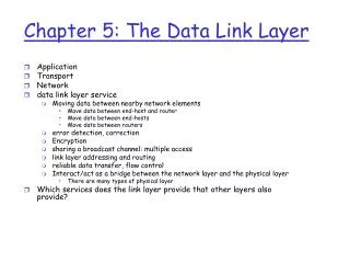
Link Layer Services • Framing, link access: • encapsulate datagram into frame, adding header, trailer • implement channel access if shared medium, • ‘physical addresses’ used in frame headers to identify source, dest • different from IP address! • Reliable delivery between two physically connected devices: • we learned how to do reliable delivery over an unreliable link • seldom used on low bit error link (fiber, some twisted pair) • wireless links: high error rates • Q: why both link-level and end-end reliability? 5: DataLink Layer
Link Layer Services (more) • Flow Control: • pacing between sender and receivers • Error Detection: • errors caused by signal attenuation, noise. • receiver detects presence of errors: • signals sender for retransmission or drops frame • Error Correction: • receiver identifies and corrects bit error(s) without resorting to retransmission 5: DataLink Layer
LAN technologies Data link layer so far: • services, error detection/correction, multiple access Next: LAN technologies • Ethernet • hubs, bridges, switches • 802.11 • PPP • ATM 5: DataLink Layer
Ethernet “dominant” LAN technology: • cheap $20 for 100Mbs! • first widely used LAN technology • Simpler, cheaper than token LANs and ATM • Kept up with speed race: 10, 100, 1000 Mbps Metcalfe’s Ethernet sketch 5: DataLink Layer
Ethernet Frame Structure Sending adapter encapsulates IP datagram (or other network layer protocol packet) in Ethernet frame Preamble: • 7 bytes with pattern 10101010 followed by one byte with pattern 10101011 • used to synchronize receiver, sender clock rates 5: DataLink Layer
Ethernet Frame Structure (more) • Addresses: 6 bytes, frame is received by all adapters on a LAN and dropped if address does not match • Type: indicates the higher layer protocol, mostly IP but others may be supported such as Novell IPX and AppleTalk) • CRC: checked at receiver, if error is detected, the frame is simply dropped 5: DataLink Layer
Ethernet: uses CSMA/CD A: sense channel, if idle then { transmit and monitor the channel; If detect another transmission then { abort and send jam signal; update # collisions; delay as required by exponential backoff algorithm; goto A } else {done with the frame; set collisions to zero} } else {wait until ongoing transmission is over and goto A} 5: DataLink Layer
Ethernet’s CSMA/CD (more) Jam Signal: make sure all other transmitters are aware of collision; 48 bits; Exponential Backoff: • Goal: adapt retransmission attempts to estimated current load • heavy load: random wait will be longer • first collision: choose K from {0,1}; delay is K x 512 bit transmission times • after second collision: choose K from {0,1,2,3}… • after ten or more collisions, choose K from {0,1,2,3,4,…,1023} 5: DataLink Layer
Ethernet Technologies: 10Base2 • 10: 10Mbps; 2: under 200 meters max cable length • thin coaxial cable in a bus topology • repeaters used to connect up to multiple segments • repeater repeats bits it hears on one interface to its other interfaces: physical layer device only! 5: DataLink Layer
10BaseT and 100BaseT • 10/100 Mbps rate; latter called “fast ethernet” • T stands for Twisted Pair • Hub to which nodes are connected by twisted pair, thus “star topology” • CSMA/CD implemented at hub 5: DataLink Layer
10BaseT and 100BaseT (more) • Max distance from node to Hub is 100 meters • Hub can disconnect “jabbering adapter” • Hub can gather monitoring information, statistics for display to LAN administrators 5: DataLink Layer
Gbit Ethernet • use standard Ethernet frame format • allows for point-to-point links and shared broadcast channels • in shared mode, CSMA/CD is used; short distances between nodes to be efficient • uses hubs, called here “Buffered Distributors” • Full-Duplex at 1 Gbps for point-to-point links 5: DataLink Layer
Ethernet Limitations Q: Why not just one big Ethernet? • Limited amount of supportable traffic: on single LAN, all stations must share bandwidth • limited length: 802.3 specifies maximum cable length • large “collision domain” (can collide with many stations) • How can we get around some of these limitations? 5: DataLink Layer
Hubs • Physical Layer devices: essentially repeaters operating at bit levels: repeat received bits on one interface to all other interfaces • Hubs can be arranged in a hierarchy (or multi-tier design), with backbone hub at its top 5: DataLink Layer
Hubs (more) • Each connected LAN referred to as LAN segment • Hubs do not isolate collision domains: node may collide with any node residing at any segment in LAN • Hub Advantages: • simple, inexpensive device • Multi-tier provides graceful degradation: portions of the LAN continue to operate if one hub malfunctions • extends maximum distance between node pairs (100m per Hub) 5: DataLink Layer
Hub limitations • single collision domain results in no increase in max throughput • multi-tier throughput same as single segment throughput • individual LAN restrictions pose limits on number of nodes in same collision domain and on total allowed geographical coverage • cannot connect different Ethernet types (e.g., 10BaseT and 100baseT) 5: DataLink Layer
Switches/Bridges • Link Layer devices: operate on Ethernet frames, examining frame header and selectively forwarding frame based on its destination • Switch isolates collision domains since it buffers frames • When frame is to be forwarded on segment, switch uses CSMA/CD to access segment and transmit 5: DataLink Layer
Switches (more) • Switch advantages: • Isolates collision domains resulting in higher total max throughput, and does not limit the number of nodes nor geographical coverage • Can connect different type Ethernet since it is a store and forward device • Transparent: no need for any change to hosts LAN adapters 5: DataLink Layer
Switch: frame filtering, forwarding • Switches filter packets • same-LAN -segment frames not forwarded onto other LAN segments • forwarding: • how to know which LAN segment on which to forward frame? • looks like a routing problem (more shortly!) 5: DataLink Layer
Backbone Switch 5: DataLink Layer
Interconnection Without Backbone • Not recommended for two reasons: - single point of failure at Computer Science hub - all traffic between EE and SE must path over CS segment 5: DataLink Layer
Switch Filtering • Switch learn which hosts can be reached through which interfaces: maintain filtering tables • when frame received, switch “learns” location of sender: incoming LAN segment • records sender location in filtering table • filtering table entry: • (Node LAN Address, Switch Interface, Time Stamp) • stale entries in Filtering Table dropped (TTL can be 60 minutes) 5: DataLink Layer
Switch Filtering • filtering procedure: ifdestination is on LAN on which frame was received then drop the frame else{ lookup filtering table if entry found for destination then forward the frame on interface indicated; else flood; /* forward on all but the interface on which the frame arrived*/ } 5: DataLink Layer
Switch Learning: example Suppose C sends frame to D and D replies back with frame to C • C sends frame, switch has no info about D, so floods to both LANs • switch notes that C is on port 1 • frame ignored on upper LAN • frame received by D 5: DataLink Layer
Switch Learning: example • D generates reply to C, sends • switch sees frame from D • switch notes that D is on interface 2 • switch knows C on interface 1, so selectively forwards frame out via interface 1 5: DataLink Layer
Disabled Spanning Tree • for increased reliability, desirable to have redundant, alternate paths from source to dest • with multiple simultaneous paths, cycles result - bridges may multiply and forward frame forever • solution: organize bridges in a spanning tree by disabling subset of interfaces 5: DataLink Layer
Spanning Tree Algorithm 5: DataLink Layer
Ethernet Switches • Sophisticated bridges • Switches usually switch in hardware, bridges in software • large number of interfaces • Like bridges, layer 2 (frame) forwarding, filtering using LAN addresses • Can support combinations of shared/dedicated, 10/100/1000 Mbps interfaces 5: DataLink Layer
Switching • Switching: A-to-B and A’-to-B’ simultaneously, no collisions • cut-through switching: frame forwarded from input to output port without awaiting for assembly of entire frame • slight reduction in latency • Store and forward switching: entire frame received before transmission out an output port • Fragment-free switching: compromise, before send out the output port receive enough of the packet to do some error checking (ex. detect and drop partial frames) 5: DataLink Layer
Common Topology Dedicated Shared 5: DataLink Layer
Bridges vs. Switches vs. Routers • Switches = sophisticated multi-port bridges • All store-and-forward devices • routers: Layer 3 (network layer) devices • Bridges/switches are Layer 2 (Link Layer) devices • routers maintain routing tables, implement routing algorithms • Bridges/switches maintain filtering tables, implement filtering, learning and spanning tree algorithms 5: DataLink Layer
Routers vs. Switches Switches + and - + Switch operation is simpler requiring less processing bandwidth - Topologies are restricted with bridges: a spanning tree must be built to avoid cycles - Switch do not offer protection from broadcast storms (endless broadcasting by a host will be forwarded by a bridge) 5: DataLink Layer
Routers vs. Switches Routers + and - + arbitrary topologies can be supported, cycling is limited by TTL counters (and good routing protocols) + provide firewall protection against broadcast storms - require IP address configuration (not plug and play) - require higher processing bandwidth • Switches do well in small (few hundred hosts) while routers used in large networks (thousands of hosts) 5: DataLink Layer
Summary • Layer 3 Devices (Network Layer) • Router • Layer 2 Devices (Link Layer) • Bridge • Switch • Layer 1 Devices (Physical Layer) • Repeaters • Hubs 5: DataLink Layer
IEEE 802.11 Wireless LAN • wireless LANs: untethered (often mobile) networking • IEEE 802.11 standard: • MAC protocol • unlicensed frequency spectrum: 900Mhz, 2.4Ghz • Basic Service Set (BSS) (a.k.a. “cell”) contains: • wireless hosts • access point (AP): base station • BSS’s combined to form distribution system (DS) 5: DataLink Layer
Ad Hoc Networks • Ad hoc network: IEEE 802.11 stations can dynamically form network without AP • Applications: • “laptop” meeting in conference room, car • interconnection of “personal” devices • battlefield • IETF MANET (Mobile Ad hoc Networks) working group 5: DataLink Layer
IEEE 802.11 MAC Protocol: CSMA/CA 802.11 CSMA: sender - if sense channel idle for DISF sec. then transmit entire frame (no collision detection) -ifsense channel busy then binary backoff 802.11 CSMA receiver: if received OK return ACK after SIFS 5: DataLink Layer
IEEE 802.11 MAC Protocol 802.11 CSMA Protocol: others • NAV: Network Allocation Vector • 802.11 frame has transmission time field • others (hearing data) defer access for NAV time units 5: DataLink Layer
Hidden Terminal effect • hidden terminals: A, C cannot hear each other • obstacles, signal attenuation • collisions at B • goal: avoid collisions at B • CSMA/CA: CSMA with Collision Avoidance 5: DataLink Layer
Collision Avoidance: RTS-CTS exchange • CSMA/CA: explicit channel reservation • sender: send short RTS: request to send • receiver: reply with short CTS: clear to send • CTS reserves channel for sender, notifying (possibly hidden) stations • avoid hidden station collisions 5: DataLink Layer
Collision Avoidance: RTS-CTS exchange • RTS and CTS short: • collisions less likely, of shorter duration • end result similar to collision detection • IEEE 802.11 allows: • CSMA • CSMA/CA: reservations • polling from AP 5: DataLink Layer
Token Passing: IEEE802.5 standard • 4 Mbps • max token holding time: 10 ms, limiting frame length • SD, ED mark start, end of packet • AC: access control byte: • token bit: value 0 means token can be seized, value 1 means data follows FC • priority bits: priority of packet • reservation bits: station can write these bits to prevent stations with lower priority packet from seizing token after token becomes free 5: DataLink Layer
Token Passing: IEEE802.5 standard • FC: frame control used for monitoring and maintenance • source, destination address: 48 bit physical address, as in Ethernet • data: packet from network layer; checksum: CRC • FS: frame status: set by dest., read by sender • set to indicate destination up, frame copied OK from ring • limited number of stations: 802.5 have token passing delays at each station 5: DataLink Layer
Point to Point Data Link Control • one sender, one receiver, one link: easier than broadcast link: • no Media Access Control • no need for explicit MAC addressing • e.g., dialup link, ISDN line • popular point-to-point DLC protocols: • PPP (point-to-point protocol) • HDLC: High level data link control 5: DataLink Layer
PPP Design Requirements [RFC 1557] • packet framing: encapsulation of network-layer datagram in data link frame • carry network layer data of any network layer protocol (not just IP) at same time • ability to demultiplex upwards • bit transparency: must carry any bit pattern in the data field • error detection (no correction) • connection liveness: detect, signal link failure to network layer • network layer address negotiation: endpoint can learn/configure each other’s network address 5: DataLink Layer
PPP non-requirements • no error correction/recovery • no flow control • out of order delivery OK • no need to support multipoint links (e.g., polling) Error recovery, flow control, data re-ordering all relegated to higher layers!| 5: DataLink Layer
PPP Data Frame • Flag: delimiter (framing) • Address: does nothing (only one option) • Control: does nothing; in the future possible multiple control fields • Protocol: upper layer protocol to which frame delivered (eg, PPP-LCP, IP, IPCP, etc) 5: DataLink Layer
PPP Data Frame • info: upper layer data being carried • check: cyclic redundancy check for error detection 5: DataLink Layer