Download
1 / 27
270 likes | 278 Vues
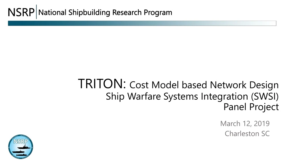
TRITON: Cost Model based Network Design Ship Warfare Systems Integration (SWSI) Panel Project. Presented by: John Mazurowski. March 12, 2019. Charleston SC. DISTRIBUTION STATEMENT A: Approved for public release. Outline. Participants Motivation Technical Approach

E N D
TRITON: Cost Model based Network DesignShip Warfare Systems Integration (SWSI)Panel Project Presented by: John Mazurowski March 12, 2019 Charleston SC DISTRIBUTION STATEMENT A: Approved for public release.
Outline • Participants • Motivation • Technical Approach • Architecture / Topology • Business Case • Roadmap
Participants Acknowledgement: Lockheed-Martin, Moorestown NJ
Overall Goals • SOLVEthe issue of cable weight and complexity • ASSESSoptical networks’ ability (cost / performance) to achieve functional goals using subsystem examples • REDUCE COST of shipboard cabling acquisition and ownership Courtesy: Lockheed-Martin
FROM TO We considered cabling designs for several subsystems and are optimizing a common network architecture that enables more efficient use by shipbuilders and system manufacturers. The cabling system will be useful over the lifetime of the ship with much less weight and complexity. Equipment upgrades cost much less because the necessary cabling is already in place. Present ship cabling is “build-to-print” based on supplier equipment designs and interconnect requirements. Cabling then becomes a major part of the shipbuilding process, especially for ships that contain large numbers of combat systems. The consequence is expensive, heavy, complex, and costly cabling. Substantial equipment manufacturer involvement is needed to deploy and maintain the systems.
User Needs Data available at any compartment that would need it; to a user, the network would appear to be a cloud. Comply with requirements for system isolation and recovery from damage. Comply with NAVSEA system design, installation, and maintenance requirements. Supply ecosystem supports the technology. Reduce upgrade cost significantly from the pattern of complete removal and replacement.
Benefits Standard optical network backbone infrastructure, installed at the shipyard, that remains useful over the lifetime of the ship. Standard interfaces for furnished equipment that facilitate low cost upgrades and quick adjustments from mission to mission. Future-proof network capacity provided through use of multiplexed optical signals transmitted through single mode fiber. Use of NAVSEA approved cabling components throughout the optical network backbone.
Optical Networks Provide • CAPACITY: Ability to keep pace with increasing need for bandwidth • ACCESSIBILITY: Access to data and systems from any compartment • RESILIENCE: Use mesh topology / control for quick damage recovery • LIFE CYCLE SUPPORT: Shipyard installs optical backbone infrastructure that functions over the ship lifetime • ADAPTATION ELEMENTS between the backbone and client equipment, used for mission changes and upgrades
Risks High network capacity puts emphasis on impairment-free fiber interconnections. Network management and control is now owned by the ship and must be administered properly. Equipment upgrades that require significant physical reconstruction could possibly affect the backbone network.
Technical Approach There is a hierarchy of optimization steps used that can reduce life cycle cost while complying with the described user needs.
A) Transmission using optical fiber System System Electrical OEO OEO Optical System System (2 X OEO + Optical Cable) < Electrical Cable
C) Wavelength Division Multiplexing System System System System System System System System System MUX DEMUX System System System (2 X MUX + WDM Fiber) < Individual Fibers
D) Use WDM-LAN hierarchy Network Management and Control (NM&C) Client or Application Client Access Interface (CAI)- Electrical Interface to Client Client Adaptation Element (CAE) Network Access Interface (NAI)- Fiber Interface at Add / Drop Level Optical Network Element (ONE) Backbone Network Interface (BNI)- Transparent Fiber Interconnect (to other ONEs) From SAE: AS5659
D (cont)Use WDM-LAN hierarchy From: Kobrinski, Perspecta Labs
E) Accommodate backbone and local capacity Connectors / splices Media Converter Optical 1x2 Star OR 1x2 switch Optical 1x2 Star OR 1x2 switch Electrical 1Gb/s 2Gb/s 2.5Gb/s 10Gb/s Electrical 1Gb/s 2Gb/s 2.5Gb/s 10Gb/s (w) (p) WDM link OTM-1 OTM-2 Short reach local WDM links may also save space and cost. Electrical: 100Mb/s or 1Gb/s Ethernet, RS-232, … (w): WDM working path (p): WDM protection path
F) Optimize interconnections Multi-Fiber Connector Fusion Splicing (preferred) From: TE Connectivity From: Corning Incorporated Risk of optical transmission impairments must be mitigated.
Project statement of work Task 1: Identify architectures, technology, applications, and associated interface protocols and required adaptation (Ingalls Shipbuilding, Penn State ARL, and Perspecta Labs). Task 2: Construct cost model for selected variants (Penn State ARL and Perspecta Labs). Task 3: Optimize interconnect methods considering single mode fiber and fusion splicing technologies for key interfaces (Ingalls Shipbuilding, Penn State ARL and Perspecta Labs). Task 4: Develop a technology implementation roadmap identifying steps needed for future USN implementation, including outline of WDM testbed using existing facilities (Ingalls Shipbuilding, Penn State ARL and Perspecta Labs).
Architectures • Other architectures / topologies considered: • Ring: added loss after 1 or 2 hops could • result in extensive need for amplifiers; • not suited for hub-type demand • Full (physical) mesh – requires more fiber • and WDM systems than switched approach
Selectedsubsystems • A-heavy computing data load • B-mixed traffic to outboard systems • C- low bandwidth multi-channel traffic • D-mixture of local and backbone traffic • E-mixture of video, analog, digital Selected subsystems had been identified as compatible with optical networks.
Typical component costs Costs used were estimates based on public data.
Cost model results • Subsystem cost model results predict: • Acquisition cost reduced by > 50% • Upgrade cost at a single node reduced > 80%
Acknowledgements The cost model was developed under the National Shipbuilding Research Program (NSRP) Panel Project Number 2016-426 “Paradigm for Optical Networks” Connection methods (fusion splicing) were analyzed under the National Shipbuilding Research Program (NSRP) Panel Project Number 2015-442 ”Alternatives to Fiber Optic Connectors”