Download
1 / 94
940 likes | 1.15k Vues
CONST 150 LAB 1 SOLDERING. SOLDERING SAFETY TIPS. Wear eye protection. Work in a well-ventilated area. Do not put wires or solder in your mouth. Wash your hands when you are finished. BASIC REQUIREMENTS. Clean metal surfaces Clean, tinned soldering iron Correct solder and flux

E N D
SOLDERING SAFETY TIPS • Wear eye protection. • Work in a well-ventilated area. • Do not put wires or solder in your mouth. • Wash your hands when you are finished.
BASICREQUIREMENTS • Clean metal surfaces • Clean, tinned soldering iron • Correct solder and flux • Correct temperature and time The actual methods used depend on the tools and materials at hand, the physical nature of the parts and boards, and the skill of the worker.
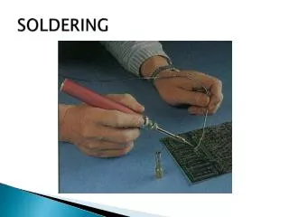
Electronic hand soldering is typically accomplished by quickly heating the metal parts to be joined, and then applying flux and solder to the mating surfaces. The flux is often supplied automatically by using wire shaped solder with a hollow core. The flux is usually rosin and is contained within the core. A finished solder joint is a metallurgical bond. Soldering forms an electrical connection between the parts and a mechanical joint. Heat is supplied with a soldering iron or other means. The flux is a chemical cleaner which prepares the hot surfaces for the molten solder by dissolving any oxide films on the metal parts. Also, and perhaps more importantly, the flux coats and prevents the heated base metals from oxidizing. The solder is a low melting point alloy of non ferrous metals. The melting point of most electronic solder is approximately 370 °F and the iron tip temperature is around 650 °F or more.
When an alloy, such as solder, is heated it typically goes thorough three phases. It goes from a solid phase to a plastic phase (halfway between a liquid and a solid) and then to a liquid phase. Eutectic solder is an alloy with no plastic phase. The eutectic alloy is made up of 63% tin and 37% lead. The plastic phase is not desirable because additional heat is required to reach the liquid phase and the additional heat can damage parts and circuit boards. Eutectic tin/lead solder has the lowest possible melting temperature (361 °F). Eutectic solder changes to a liquid just above the melting point and, as it cools, it will transform directly into a solid. This makes it possible to quickly form superior solder joints. A 60% tin and 40% lead alloy can also be used. This alloy shows an almost eutectic change from solid to a liquid and has a melting range of 361 °F to 374 °F. Another alloy is available that uses 62% tin, 36% lead and 2% silver. It has a melting range of 354 °F to 372 °F. It is preferred for surface mount chip components because it prevents silver from leeching from the components into the solder joints.
SOLDER TROUBLESHOOTING Common mistakes: 1. The metal parts are not clean. 2. The solder or the flux is not the correct type. 3. The soldering tip is too small for the joint. 4. The iron was not up to temperature or its wattage rating is too small. Some additional troubleshooting tips follow. 1. The solder won't wet (take) because grease, corrosion or is dirt present,clean up the parts, pads, wires and terminals. 2. The solder won’t wet because the material is not suitable for soldering, a special solder and/or flux might be required. 3. The joint is dull or grainy looking because a part or a wire moved before freezing, physically stabilize the assembly in a holder or by other means. 4. The joint is dull or grainy looking because the joint was improperly heated or flux is lacking. 5. The solder joint has a spike because it was overheated and all the flux burned off.
30 WATT SOLDERING IRON 80 WATT SOLDERING STATION 300 WATT SOLDERING IRON
Cleaning with wire brush Tinning the iron Cleaning by wiping tip on a damp sponge
A diameter of 0.025 inches is common for most electronic work. Eutectic alloy (lowest melting point) 63% tin, 37% lead Solder 62% tin, 36% lead, 2% silver is preferred for some work
Solder bridge A magnifier is helpful for inspection. Circuit board holder
Desoldering methods Desoldering braid Vacuum pump Vacuum desoldering station
Click the center of the photo to start the video. Using desoldering braid
Click the center of the photo to start the video. Using a vacuum pump
Click the center of the photo to start the video. Using a vacuum desoldering station
After device removal Clean the pads with desoldering braid
Click the center of the photo to start the video. Soldering Apply the iron, then the solder. Remove the solder, then the iron. (About 3 seconds per lead)
Click the center of the photo to start the video. Clean the area Spray with flux cleaner and then brush to remove flux residue.
LAB#2 SIMPLE SERIES CIRCUITS IN THIS LAB WE WILL START WITH A SIMPLE CIRCUIT AND GRADUALY MADE IT MORE COMPLEX. CONSTRUCT THE CIRCUIT SHOWN BELOW ON THE PLYWOOD PROTOTYPE BOARD. VOLTMETER V Sw R 200Ω 12VDC FROM POWER SUPPLY LED, ANY COLOR Collin's Lab: The REAL Breadboard http://www.youtube.com/watch?v=HrG98HJ3Z6w
LED’S ARE POLARITY SENSITIVE (MORE ABOUT THIS LATER) MAKE SURE THEY ARE CONNECTED THE WAY I SHOWED YOU. V Sw R 200Ω LED 12VDC
MEASURE THE VOLTAGE USING YOUR MULTIMETER AT THE POWER SUPPLY, ACROSS THE RESISTOR AND THE LED. V Sw R 200Ω LED 12VDC VARY THE VOLTAGE FROM THE POWER SUPPLY. WHAT HAPPENS TO THE LED.
MEASURE THE CURRENT IN THIS CIRCUIT WITH AN AMMETER. AMMETER’S MUST BE PLACED IN THE CURRENT PATH, NOT ACROSS IT. V Sw R 200Ω 12VDC LED I MOVE THE AMMETER AROUND THE CIRCUIT IS THEIR ANY DIFFERENCE IN THE CURRENT MEASURED?
MAKE AN OPEN CIRCUIT BY DISCONNECTING THE LED. WHAT HAPPENS TO THE VOLTAGE AND CURRENT. V Sw R 200Ω LED 12VDC I
PLACE A JUMPER WIRE FROM THE RESISTOR ACROSS THE LED. WHAT HAPPENS TO THE VOLTAGE AND CURRENT READINGS. V Sw R 200Ω LED 12VDC I
PLACE A FUSE HOLDER( WITH FUSE) BETWEEN THE POWER SUPPLY AND THE ON/OFF SWITCH. TRY TO FIGURE OUT A APPROPRIATE AMPERE RATING FOR THE FUSE. V F Sw 200Ω LED 12VDC
NOW REPLACE THE LED WITH A DIFFERENT LOAD, A COMPUTER COILING FAN. CHECK THE VOLTAGE AND CURRENT READINGS WITH THE FAN. ANY DIFFERENCE. WHY? V Sw F 200Ω 12VDC FAN I
NOW REPLACE THE SWITCH WITH A POTENTIOMETER. THIS WILL ALLOW YOU TO VARY THE VOLTAGE ACROSS THE LOAD, BRIGHTEN OR DIM THE LED, CHANGE THE FAN SPEED V F Sw VR 200Ω LED 12VDC FAN I
SINCE ALL UTILITY POWER SUPPLIED IS ALTERNATING CURRENT( A/C) AND ALL ELECTRONIC CIRCUITS RUN ON DC WE NEED A MEANS OF CONVERTING AC TO DC THIS IS DONE WITH THE USE OF A TRANSFORMER. IN OUR CASE WE ARE USING A STEP DOWN TRANSFORMER. TAKING A HIGHER VOLTAGE A/C AND DROPING IT TO A LOWER VOLTAGE A/C. WE THEN CONVERT THIS LOW VOLTAGE AC TO DC WITH A DIODE (OUR FIRST LOOK AT A SIMPLE RECTIFIER). V F D2 VR 200Ω Sw D1 12V AC 120V AC FAN IN4001 I
Wall clocks, mp3 players, electronic sensors, and special devices use 1.5V battery (cell) as power source. We sometimes forgot to buy or replace the battery but no worries because we can design circuits that can convert higher DC voltages to useable 1.5V.The following electronic circuits are possible schematic of 1.5V power sources or regulators.Simple 1.5V power supplyAround 20mA maximum output current, good in low power application like wall clocks. Part List:R- 220 ohms 1/4WD - 1N4001 or similar diodeLED - 3mm or 5mm red LEDC - 4.7uF electrolytic capacitorDC - 4V to 6V DC source