Download
1 / 9
90 likes | 245 Vues
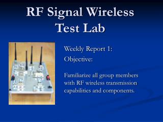
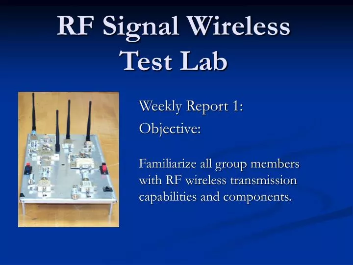
RF Signal Wireless Test Lab. Weekly Report 1: Objective: Familiarize all group members with RF wireless transmission capabilities and components. RF Signal Wireless Test Lab.

E N D
RF Signal Wireless Test Lab Weekly Report 1: Objective: Familiarize all group members with RF wireless transmission capabilities and components.
RF Signal Wireless Test Lab • We met with Graduate Research Assistants and discussed possible objectives as to how we can enhance certain concepts of the original design. • Researched devices such as Mixers, Filters, Circuit Designs, Oscillators, Amplifliers, and RF Signal Generators for Base Band Frequency • Familiarize ourselves with the actual design and breakdown the frequency receiver/transmitter capabilities for the 900 MHz and 2.4 GHz frequency signals. • Arranged lab access hours with Graduate Research Assistants for further weekly meetings.
RF Signal Wireless Test Lab Communication Systems - Overview TRANSMITTER RECEIVER Information input Transmission medium (channel) ~ Signal processing Signal processing Carrier circuits s(t) r(t) Carrier circuits m(t) m(t) To information sink (user) • There are 3 basic elements to every communication system: • Transmitter: converts the message signal produced by the source of information into a form suitable for transmission over the channel. • Channel: physical medium that connects the transmitter and receiver. • Receiver: operates on the received signal so as to reconstruct a recognizable form of the original message signal.
RF Signal Wireless Test Lab Frequency Bands Propagation Characteristics LOS propagation, cosmic noise LOS propagation; rainfall attenuation above 10 GHz, atmospheric attenuation because of oxygen and water vapor, high water vapor absorption at 22.2 GHz Typical Users VHF television, FM two-way radio, AM aircraft communication, aircraft navigational aids UHF television, cellular telephone, navigational aids, radar, GPS, microwave links, personal communication systems Frequency Band 0.3-3 GHz 3-30 GHz Designation Ultrahigh Frequency (UHF) Superhigh Frequency (SHF)
RF Signal Wireless Test Lab Components used in original design: • Amplifier: enhances current signal to allow stronger frequency • Filter (low-pass): bypass unwanted high-frequency signals • Mixer – combine both base band and oscillated frequency signals into one • Oscillator – generates frequency signal for a determined value • Signal Generator – provides base band frequency through an external median
RF Signal Wireless Test Lab Previous Design • Current Design is able to transmit a 900 Mhz and 2.4 MHz frequency • The 5.7 MHz transmission capability has been redesigned due to excessive voltage provided by power generator/splitter • Efficient in providing consistent results for given frequency capabilities
RF Signal Wireless Test Lab Proposed Design • Take the current design layout for the 900Mhz and 2.4 GHz transmission rate and redesign platform onto a PCB( printed circuit board ) • Modifying current 5.7 GHz transmitter/receiver design onto new model • Find a constructive Application process for the given frequencies once implemented onto PCB
RF Signal Wireless Test Lab The Next Step - Report 2 • We will have a finished layout of website where all presentations, progress reports, and research papers will be available for viewing • Test the 5.7 GHz frequency design to see what improvements can be made • Start researching components for proposed PCB model