Download

1 / 28
721 likes | 2.19k Vues
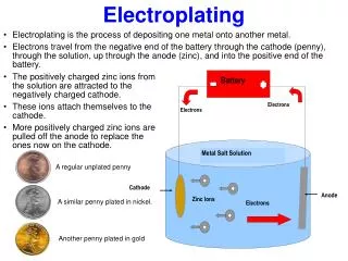
Electroplating. Recommendations for a new and independent setup. +. -. DC POWER SUPPLY. Current Setup. Pura Gold 401 Solution Copper electrode Glass beaker Plastic sample plate Gold electroplated copper holds down sample Sample (e.g. InGaAs) Platinum electrode. Hot Plate (w/ stirrer)

E N D
Electroplating Recommendations for a new and independent setup
+ - DC POWER SUPPLY Current Setup Pura Gold 401 Solution Copper electrode Glass beaker Plastic sample plate Gold electroplated copper holds down sample Sample (e.g. InGaAs) Platinum electrode Hot Plate (w/ stirrer) Temperature = 60°C
+ - DC POWER SUPPLY Current Setup Pura Gold 401 Solution • Contents: • Distilled water (85%) • Non-hazardous salts (20%) • Potassium Gold Cyanide (2%) • Thallium (0.1%) • Other soluble compounds • Manufacturer: • Ethone-OMI Inc. • New Haven, CT Hot Plate (w/ stirrer) Temperature = 60°C
+ - DC POWER SUPPLY Current Setup Copper electrode • Copper used because: • Good electrical conductor • Relatively inexpensive(?) Hot Plate (w/ stirrer) Temperature = 60°C
+ - DC POWER SUPPLY Current Setup Glass beaker • Glass used because: • Handles heat well • Inexpensive Hot Plate (w/ stirrer) Temperature = 60°C
+ - DC POWER SUPPLY Current Setup Plastic sample plate • Plastic used because: • Does not dissolve in bath • Insulator, so gold does not adhere Hot Plate (w/ stirrer) Temperature = 60°C
+ - DC POWER SUPPLY Current Setup Gold electroplated copper holds down sample • Gold from solution adheres to copper (wasteful), so keep sample as close to surface as possible • Transfers (-) polarity to sample Hot Plate (w/ stirrer) Temperature = 60°C
+ - DC POWER SUPPLY Current Setup Sample (e.g. InGaAs) • Desired plating thickness: 9 µm • Time in bath: ~90min Hot Plate (w/ stirrer) Temperature = 60°C
+ - DC POWER SUPPLY Current Setup Platinum electrode • Electrically conductive • Won’t dissolve in bath Hot Plate (w/ stirrer) Temperature = 60°C
+ - DC POWER SUPPLY Current Setup Parameters • Temperature: 60±10°C • Direct current: ~3mA • Negative photoresist • Photoresist bake ~1hr • Heat solution ~ 1hr • Plating ~1.5hr • Liftoff ~8 hours • Total Time: ~3 hours attended plus overnight unattended Hot Plate (w/ stirrer) Temperature = 60°C
+ - DC POWER SUPPLY Current Setup PROBLEMS • Cyanide highly toxic and environmentally unfriendly • Cyanide eats under photoresist if not baked properly, causing plating in undesired areas • Negative photoresist required, meaning long liftoff times • Evaporation makes replenishing solution frequently necessary • Copper holder too large for tiny sample • Gold shrinks during cooling at different rate from semiconductors, putting strain on sample Hot Plate (w/ stirrer) Temperature = 60°C
Possible New Strategies • Replace Platinum anode with Titanium or Cadmium coated with Platinum (if this is not currently the case), reducing cost • Alternative plating materials • Cyanide vs. non-cyanide baths • Electroless plating • Back-side plating • Computerized process
Alternative plating materials • Important factors: • Thermal Conductivity • Plating designed for cooling • Adhesion • Must adhere well to III-V compounds in samples and copper in heat sink • Density • Denser plating means better properties • Thermal Expansion Coefficient • When cooling occurs, a TEC different from that of the plated material causes stress on the system
Alternative plating materials From Graham, A. Kenneth, ed. Electroplating Engineering Handbook. New York: Van Nostrand Reinhold Co. 1971. p12-15.
Alternative plating materials From Graham, A. Kenneth, ed. Electroplating Engineering Handbook. New York: Van Nostrand Reinhold Co. 1971. p12-15.
Alternative plating materials Thermal expansion coefficients of commonly-used semiconductors (x10-6/°C): AlAs: 5.20 GaAs: 5.73 InAs: 4.52 InP: 4.60 In0.53Ga0.47As: 5.09 Al0.48In0.52As: 4.85 From http://www.ioffe.rssi.ru/SVA/NSM/Semicond/
Alternative plating materials Thermal expansion coefficients of commonly-used semiconductors (x10-6/°C): AlAs: 5.20 GaAs: 5.73 InAs: 4.52 InP: 4.60 In0.53Ga0.47As: 5.09 Al0.48In0.52As: 4.85
Gold – The Strategies From “Some Recent Developments in Non-Cyanide Gold Plating for Electronics Applications,” p2
Cyanide Electroplating Baths • Alkaline • pH ~11, excess of free cyanide • Sacrificial gold anode • Incompatible with many elements of microelectronics, degrades photoresist • Acid • pH ~4 with aid of citrate buffer • Anode is platinized titanium or gold • Low current densities required, slowing process • Hydrogen gas = unwanted byproduct • Neutral • pH ~7 • Anode is platinized titanium or gold • Relatively low current density (2-5mA/cm2), 60-70°C • Au(III) = unwanted byproduct (creates process control problem) From Modern Electroplating p205-213.
Cyanide vs. Non-Cyanide • Gold Cyanide complex = more stable • More widely used and available • Health/safety concerns • Lower plating efficiency • Incompatible with positive photoresists • Residual stress can be controlled in non-cyanide baths • But this uses Thallium, a health hazard From Modern Electroplating p213-14.
Non-Cyanide Baths • Thiosulfate [Au(S2O3)2]3- • Has never been used for a practical bath • Stability constant = 1026 • Thiosulfate ion itself is unstable • Sulfite: [Au(SO3)2]3- • Unstable (stability constant = 1010, as compared with 1039 for Cyanide-based [Au(CN)2]-) • Stabilizing additives required • Additives fortunately allow lower pH levels, increasing compatibility with photoresists From “Some Recent Topics in Gold Plating for Electronics Applications,” p4
Non-Cyanide Baths • Thiosulfate-Sulfite “Mixed Ligand” Bath • Highly stable even without stabilizers added • Gold deposit contains sulfur as an impurity element, increasing hardness • Sulfur content should be minimized • Advantage: pH = 6.0, making it better for standard, positive photoresists From “Some Recent Topics in Gold Plating for Electronics Applications,” p5
Non-Cyanide Baths • Both Sulfite and Thiosulfate-Sulfite baths now available commercially • Sulfite: Aurofab BP • Thiosulfate-Sulfite: ECF60mod • Advantages: • Reduction in toxicity • Compatibility with positive photoresists possible • More freedom with material of anode • Sulfite bath appears to be more widely used currently
Electroless Plating • Specifically “Autocatalytic processes,” or “Chemical reduction plating” • Eliminates need for DC source, electrodes • Reduces cost • Significant pretreatment required • Not as much control over thickness • Best Plating rate: 1.5µm/h • Resulting time in bath = 6 hrs From “Some Recent Developments in Non-Cyanide Gold Plating for Electronics Applications,” p6-10
Reducing Strain – Back-side Processing • Theoretically, equal and opposite strain from each side cancels out • I was unable to find record of back-side plating being used for strain reduction • Likely reduces adhesion, gold may detach • Perhaps the selective nature of the frontal plating makes equality of strain difficult x
Computerized process • Robotic arm performed functions as early as 1982 • Advantages: • Assured uniformity in plating thickness • Researcher need not be present(?) • Disadvantages: • Cost increase • Space issues • Available primarily for large-scale, non-research operations
Recommendations from Igor • Reference Electrode • Plastic lid (e.g. polystyrene) should be used to prevent evaporation • Better, smaller sample holder • Greater thickness control (how?) • Deposit gold in troughs just below ridges • Better heat conduction
Sources Journals: • Green, T.A., Liew, M.J., and Roy S. ,”Electrodeposition of Gold from a Thiosulfate-Sulfite Bath for Microelectronic Applications” Journal of The Electrochemical Society. v150n3 C104-C110. 2003. • Holliday, R. and Goodman, P. “Going for Gold.” IEEE Review. May 2002. p15-19. • Kato, Masaru and Okinaka, Yutaka. “Some Recent Developments in Gold Plating for Electronics Applications.” ??? p1-15. • Okinaka, Y. and Hoshino, M. “Some Recent Topics in Gold Plating for Electronics Applications.” Electrochemical Technology Applications in Electronics. Proceedings of the Third International Symposium (Electrochemical Society Proceedings Vol.99-34), 2000, p 132-44. • Wang, K., Beica, R., and Brown, N. “Soft gold electroplating from a non-cyanide bath for electronic applications.” IEEE/CPMT/SEMI 29th International Electronics Manufacturing Technology Symposium. 2004. p 242-6. • Young, E., et. al. “Characterization of Electroplated Gold for Back-Side Processing of GaAs Wafers.” 2002 GaAs MANTECH Conf. Digest of Papers. 2002. p180-3. • Osaka, T., Okinaka, Y., and Kato, M. “Non-cyanide electrolytes for electroytic and electroless gold deposition processes.” ???. Books: • Graham, A. Kenneth, ed. Electroplating Engineering Handbook. New York: Van Nostrand Reinhold Co. 1971. • Kanani, Nasser. Electroplating: Basic Principles, Processes, and Practice. Oxford: Elsevier Ltd. 2004. • Schlesinger, M. and Paunovic, M. Modern Electroplating: Fourth Edition. New York: John Wiley & Sons, Inc. 2000. Note: the Okinaka sources each present some unique information, but they do have a great deal of overlap.