Download
1 / 26
320 likes | 609 Vues
Combined Geological Modelling and Flow Simulation. TIG-10 Workshop, Adelaide 11/2010. J. Florian Wellmann, Lynn Reid, Klaus Regenauer-Lieb and the Western Australian Geothermal Centre of Excellence. Outline.

E N D
Combined Geological Modelling and Flow Simulation TIG-10 Workshop, Adelaide 11/2010 J. Florian Wellmann, Lynn Reid, Klaus Regenauer-Lieb and the Western Australian Geothermal Centre of Excellence
Outline • Addressing the problem that geological modelling and geothermal simulation are usually separated (and geological uncertainty not considered – even if significant) • Workflow to integrate both steps into one framework • Two example models: • Hypothesis testing for different geological scenarios • Combination with geological uncertainty simulation
Geological Modelling • Construction of a structural representation of the subsurface • Interpolation based on discretized geological observations (e.g. from drillholes, seismics, field work) • Applied modelling tool: GeoModeller (Intrepid Geophysics, BRGM) (Calcgano et al., 2008)
Geothermal Flow Simulation Permeability Porosity • Coupled simulation of fluid and heat transport equations in the subsurface • Based on property distribution (e.g. permeability, porosity, thermal conductivity, heat capacity) in subsurface and boundary conditions (e.g. basal heat flux) • Applied simulators: TOUGH2, SHEMAT
Discretized geological model Geological Model Property assignment Mesh Simulation Geological Data Manual steps Boundary conditions
Critical steps • Mainly related to • model construction, • mesh generation and • processing to flow simulation Once constructed, the geological model is rarely changed or extended, even if significant source of uncertainty! Steps before flow simulation
Change one data point Evaluate effect on flow field Automation steps Implicit potential-field method (GeoModellerTM); enables direct model update Geological modeling Automated rectilinear mesh discretization (python scripts) Discretization Direct update of input files for simulation with SHEMAT and TOUGH2 (python scripts) Model simulation setup Simulation with available codes, post-processing and analysis (python scripts) Simulation and analysis
near-surface heat flux (z-dir) Geological Hypothesis Testing
Combination with Uncertainty Simulation • Consider uncertainties in structural geological models (one of main sources of uncertainty) • Approach: random change of input data (discretized surface position, orientation data)
Example model North Perth Basin Wells don’t penetrate basement! Assume: structure more or less well defined (seismics) but exact position at depth unknown
Change bottom of formations randomly Position of formation bottoms changed about random value Create 20 different input data sets and 20 different models Standard deviation for data points defined at bottom of formation
Results of simulation • For 20 geological models, we obtain 20 simulated flow and heat flow fields (drawing from the uncertainty distributions) Example of one temperature model
Conclusion • Uncertainties in structural model influencesimulated geothermal flow field but they are usually not considered • Developed integrated workflow • enables hypothesis testing and consideration of geological uncertainty • compliments and extends other approaches (e.g. stochastic simulation, as presented by Tony Meixner), e.g.: • physics(multi-phase, thermo-hydro) • mesh(rectilinear) • consideration ofuncertainties in geological data(not the model) • Specifically suited for early exploration stages and resource evaluation where uncertainties in the structural model are dominant.
Outlook • Complete implementation on supercomputer • Optimal mesh construction for geological models (e.g. automatic rectilinear refinement, extruded triangular for TOUGH2) • Coupling to advanced resource estimation methods (talk at AGEC) • Combination with GIS methods Thank you for your attention!
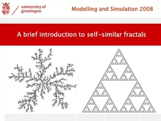
How to analyse uncertainties in structural models? Uncertainty in Geology models: different types Incomplete knowledge Are all relevant structures known?
How to analyse uncertainties in structural models? Uncertainty in Geology models: different types Uncertainty of interpolation How good is the interpolation between data points?
How to analyse uncertainties in structural models? Uncertainty in Geology models: different types Uncertainty in raw data How exact is the data? • Applies specifically to interpreted data and assumptions • We consider this to be a significant part of model uncertainties • (Wellmann et al, 2010)
Mesh geometries • Regular mesh • Rectilinear mesh • Extruded triangular mesh (only TOUGH2) (work in progress: optimal mesh generation from geological models) (Include example extruded triangular?)
Processing simulated models to simulation Coupled fluid and heat flow simulation in a 2-D subset of the model Discretization in a regular grid Two highly permeable formations
Convective vs. conductive heat transfer • Local Peclet number Pe = l v / k In our case: • l: characteristic length • v: fluid velocity (model result) • k: thermal diffusivity (10-6 m2/s) Convection dominated: high Pe-Number Conduction dominated: low Pe-Number As characteristic length scale, we use engineering lifetime of 30 years and get l approx 60 m
Example of local Pe-Numbers for one model Pex right left Pez down up