Download
1 / 23
230 likes | 456 Vues
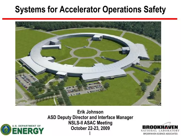
Systems for Accelerator Operations Safety. Erik Johnson ASD Deputy Director and Interface Manager NSLS-II ASAC Meeting October 22-23, 2009. What are SAOS ?. Broadly speaking systems designed to keep bad things from happening to people or equipment;

E N D
Systems for Accelerator Operations Safety Erik Johnson ASD Deputy Director and Interface Manager NSLS-II ASAC Meeting October 22-23, 2009
What are SAOS ? Broadly speaking systems designed to keep bad things from happening to people or equipment; • only permit operation when predetermined conditions are met, • provide barrier function • Technical elements identified in WBS 1.03.06 • 1.03.06.01 Personnel Protection System • 1.03.06.02 Equipment Protection System • 1.03.06.03 Area Monitoring • 1.03.06.04 Local Shielding • Elements not explicitly identified in WBS • Active interlock • Top off injection ASD + …. • Beam containment system
People working on SAOS Andrew Ackerman, Rudy Alforque, Mike Buckley, Scott Buda, Bob Casey, Bob Dalesio, Lewis Doom, David Dudley, Asher Etkin, Ray Fliller, George Ganetis, Carmine Guarino, Richard Heese, Steve Jarazabkowski, PK Job, Erik Johnson, Henry Kahnhauser, Stephen Kramer, Jerry Malley, John McCaffre, Brian Mullany, Ewart Orr, Jonathan Reich, Paul Ribaudo, Jim Rose, Timur Shaftan, Sushil Sharma, Om Singh, Ferdinand Willeke Andrew Ackerman, Rudy Alforque, Mike Buckley, Scott Buda, Bob Casey, Bob Dalesio, Lewis Doom, David Dudley, Asher Etkin, Ray Fliller, George Ganetis, Carmine Guarino, Richard Heese, Steve Jarazabkowski, PK Job, Erik Johnson, Henry Kahnhauser, Stephen Kramer, Jerry Malley, John McCaffre, Brian Mullany, Ewart Orr, Jonathan Reich, Paul Ribaudo, Jim Rose, Timur Shaftan, Sushil Sharma, Om Singh, Ferdinand Willeke Andrew Ackerman, Rudy Alforque, Mike Buckley, Scott Buda, Bob Casey, Bob Dalesio, Lewis Doom, David Dudley, Asher Etkin, Ray Fliller, George Ganetis, Carmine Guarino, Richard Heese, Steve Jarazabkowski, PK Job, Erik Johnson, Henry Kahnhauser, Stephen Kramer, Jerry Malley, John McCaffre, Brian Mullany, Ewart Orr, Jonathan Reich, Paul Ribaudo, Jim Rose, Timur Shaftan, Sushil Sharma, Om Singh, Ferdinand Willeke Andrew Ackerman, Rudy Alforque, Mike Buckley, Scott Buda, Bob Casey, Bob Dalesio, Lewis Doom, David Dudley, Asher Etkin, Ray Fliller, George Ganetis, Carmine Guarino, Richard Heese, Steve Jarazabkowski, PK Job, Erik Johnson, Henry Kahnhauser, Stephen Kramer, Jerry Malley, John McCaffre, Brian Mullany, Ewart Orr, Jonathan Reich, Paul Ribaudo, Jim Rose, Timur Shaftan, Sushil Sharma, Om Singh, Ferdinand Willeke • CAM for 1.03.06 • (talking about the work of others!) • PPS EPS Shielding • Design reviews • Integration with other systems • PPS EPS Shielding • Design reviews • Integration with other systems • PPS EPS Shielding • Design reviews • Integration with other systems
Personnel Protection Systems Design Goal Protect personnel from high radiation areas by • preventing access • controlling radiation producing devices or conditions Accomplished by integrated systems • Accelerator PPS • Linac (LPPS) • Booster (BPPS) • Storage Ring (SPPS) • Experimental Beam Lines (EPPS) S. Buda, E. Orr
NSLS-II PPS Zones 1 • PPS must allow: • Linac operable with personnel in booster • Booster operable with personnel in storage ring • Storage ring cavity testing with personnel in other pentants • Individual search of each pentant B 2 5 L 4 3
Design Features • All interlock logic trees will have redundant and independent chains • The system is fail safe for foreseeable failure modes (e.g., loss of power, open circuit, short to ground, and single component failure) • Redundant circuits will not share cables and will be separated physically on circuit boards and terminal strips • A rigorous configuration management program will be established to control unauthorized modifications to interlock system components including physical access control. • All interlock wiring and components will be labeled and readily identifiable. Wires run in dedicated conduit or segregated in cable tray. • Testing & certification of interlock systems will be performed by independent personnel. • Design for enclosure search systems will include sequenced and timed inspection stations, warning lights, audible alarms, emergency shut down switches and mirrors where necessary.
Schematic of system interactions Safety Shutter Photon Shutter PPS monitors state of safety significant components Area monitor Valve EPPS SPPS - MCCS SPPS - Cell • Interfaces with RF and Power supply systems for main beam shut off • Inputs from other systems provide go or no-go status. • Systems include: Radiation monitors, beam current, linac pulse rate Storage Ring FOE EESE Beamline EPS Front End EPS EPS mediates change in state of safety significant components HMI Panel Details of Front end in Sushil Sharmas talk
Technical Highlights • Integration of area radiation monitors with the main ring system (SPPS) ~60 locations • Main ring divided into 5 separate sections for modular concept eg each pentant has its own separate CPU • Provides search and secure function for each pentant • Main ring uses a distributed I/O architecture • Interface to Light source Two Control System (LTCS) for archiving of system data • Use of safety rated PLC’s to increase reliability and diagnostic capability
Search patterns for the storage ring Note pentants 1,3,4 and 5 are identical, pentant 2 has two entrance labyrinths. The paths are similar, but with an extra leg for the extra entrance.
Engineering Prototype • Working PPS prototype including • SPPS (pentant, front end components) • EPPS (EESE) and EPS • Confirm operation of systems together • Aid in software development and operational assumptions • Prototype saved after construction for training, troubleshooting and as a test bed for improvements • Interface development with LT Control System
Prototype SPPS Shutter proxy
Human Interlock Interface (search box) Preliminary Design Beam Imminent Beacon Search In Progress Beacon Emergency Stop Area Secure Search indicator Functional Prototype Beam Disabled Search Button Ewart Orr, Engineer Beam Imminent Siren Single Pentant Siren
Engineering Design Reviews • Personnel Protection Systems • SPPS and EESE design overview 24 September 2008 • Evaluation of design features for SPPS including safety functions 18 December 2008 • Complete evaluation of SPPS, EESE evaluation and safety functions 20 February 2009 • Injector PPS - Booster PPS and safety functions 23 April 2009 • Injector PPS – Linac PPS and safety functions 5 May 2009 • SPPS Engineering Design Plan Review 18 August 2009 • Core BNL based review team – • Andrew Ackerman, Mike Buckley, Asher Etkin, Steve Hoey, Henry Kahnhauser, Jonathan Reich (plus others when needed) • Design review of NSLS Interlock systems (SIS-TECH Solutions) • Develop and evaluate failure model for existing interlock system at NSLS • Build toolkit for SIL approach to NSLS-II PPS design • Gain valuable (and positive) experience with external analysis firm
Project perspective for PPS • Cost baseline • 1. Accelerator - Design, construct, install, test, commission • 2. Experimental - Design, prototype (construct/install costs by XFD) • Schedule baseline for PPS • FY 2009 build and test PPS engineering prototype • FY 2010 develop production design and start manufacture • FY 2011 installation & testing underway • PPS Interlock Complete June 2012
Selected specifications for area monitors • Measure photon dose rate from 10 µRem/h to 1000 mRem/h • Measure photons in the energy range from 80 KeV to several MeV • Monitor short pulse radiation < 100 nS/pulse at 1 Hz repetition rate • Provide alarm on integrated dose at predetermined set point* • Provide alarm on dose rate at predetermined set point • Provide local visual and audible indication of increased radiation levels above predetermined set points • Provide self-monitoring of detector and processor function and actuation of relay for the following conditions: System check, Loss of power, Lack of signal, Background drift* • Provide 3 sets of relay contacts for: High radiation alarm, system malfunction, warning alarm noting increased radiation levels
Area monitor plan • Fall 2009 – procure and install at NSLS several detectors for review of performance, reliability, and maintenance requirements for a period of 12 months • Winter 2010-2011 – prepare and issue area monitoring specifications and request for bid • April 2011 – Award contract for radiation monitoring system • December 2011 – Receive at least 30 units for inspection and test • February 2012 – Linac area monitoring system operation • June 2012 – Booster area monitoring system operation • July 2012 – Receive balance of detectors • November 2012 – Ring building area monitoring system operational
Strategy for Supplementary Shielding • Injection / extraction septa and beam dumps shielded for fast injection rate of 15 nC/s • Probable high beam loss points (injection / extraction regions) shielded with additional supplementary shielding • Beam loss at non-injection regions will be controlled by engineering solutions of BCS systems (see Bob Casey talk) • Shadow shields inside the booster to protect occupiable regions from forward peaking tangential bremsstrahlung due to beam loss • Shielding at the storage ring injection septum • Shielding around beam pipe penetrations from the accelerator enclosures, including the ratchet wall collimator • Bremsstrahlung stops at the dummy front ends with no beamlines
Linac Shielding SAFETY SHUTTER LOCAL SHILEDING 2 2 BEAM DUMPS SLIT SHIELDING R. Alforque LOCAL SHIELDING 1
Critical Devices for the Radiation Enclosures Linac • Electron Gun • Klystron Power Supplies Booster • Linac to Booster transport line Dipole Magnet • Linac to booster transport line Safety Shutter • Booster RF Power Supply • Booster Dipole Magnet Power Supply Storage Ring • Booster to SR transport line Dipole Magnet • Booster to SR transport line Safety Shutter • SR RF Power Supply • SR Bending Magnet Power Supply First Optics Enclosure • Redundant Safety Shutters Experimental Stations • Redundant Monochromatic Shutters
Issues and Conclusions Issues on the horizon • Refine definition of interfaces with control system and control room • Finalize interface requirements for Top-off and Beam containment systems as their designs mature Conclusions • Interfaces between SAOS systems identified and/or specified (affordances included for ‘extras’) • Focus on prototype system construction and testing in near term • Move into production of PPS systems in FY10 for FY11 installation start • VE choices and design evolution are pushing progress well ahead of baseline schedule and under budget • Will have thoroughly characterized systems deployed for installation and commissioning