Download
1 / 43
1.71k likes | 5.14k Vues
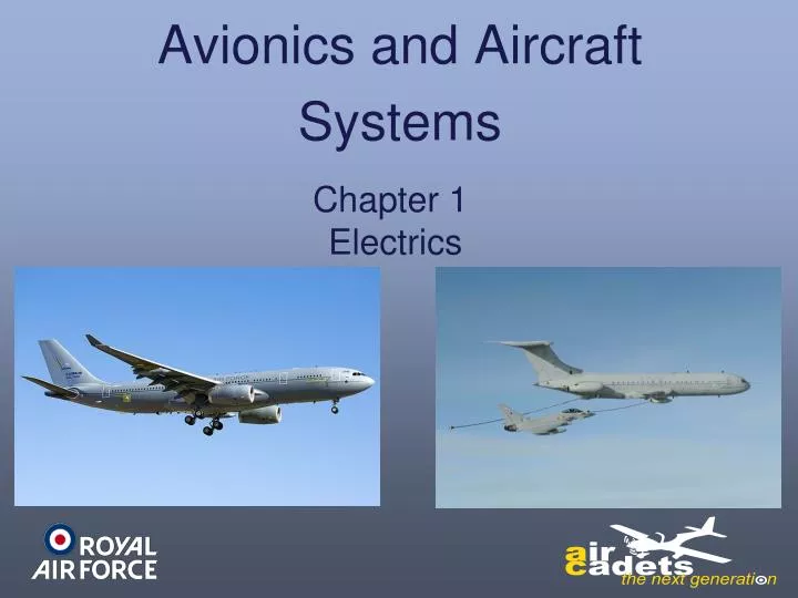
Avionics and Aircraft Systems. Chapter 1 Electrics. Aircraft Electrical Power Supplies. Electricity is the life blood of any modern aircraft. Just about every action on an aircraft requires electricity either to control the action, power the action or monitor the action.

E N D
Avionics and Aircraft • Systems Chapter 1 Electrics
Aircraft Electrical Power Supplies Electricity is the life blood of any modern aircraft. Just about every action on an aircraft requires electricity either to control the action, power the action or monitor the action.
Aircraft Electrical Power Supplies Alternating Current (AC) 3 Phase (Ø) 115 Volt 400Hz Direct Current (DC) 28 Volt First lets look at AC
Definitions Electrical Systems Electro Motive Force (EMF): A power source which causes the electrons to move continuously and normally comes from a generator or battery. Direct Current (DC): A flow of electrons in an external circuit from the negative to the positive terminals of the supply. Alternating Current (AC): A flow of electrons which periodically reverses it’s direction, reaching a maximum first in one direction then in the other. Resistance: Is the opposition to electron flow and is measured in Ohms. Current: Is the flow of electrons through a circuit and is measured in Amperes. When an electron flow meets a resistance an EMF is required to push them through. The same number of electrons enter and leave a resistance but the EMF at the input side will be greater than the EMF at the output side. The difference between these two forces is the Potential Difference or Volts Drop and is measured in Volts. Potential Difference: Busbar: A strip of metal which has a power supply attached to one side of it and load circuits attached to the other side.
Electrical Systems Definitions Generator: A rotating device which produces either AC or DC voltage. Battery: A unit that stores an EMF and is a combination of cells, each of which is a device for converting chemical to electrical energy. Transformer: A static device that changes the amplitude or phase of an AC current or voltage by electromagnetic induction. Transformer Rectifier Unit (TRU): A device which changes AC electric into DC electric. Inverter: A device which changes DC electric into AC electric. It does this by using a DC motor to drive an AC generator. Relay: A device which when power is applied makes a set or sets of contacts to connect parts of an electrical circuit. When power is removed the relay relaxes. Latched Relay: A relay which is powered instantaneously and held in position mechanically. To release the relay a second instantaneous application of power is required.
Electrical Systems Alternating Current (AC) By rotating a wire loop between 2 magnets of opposite poles electricity is produced. The polarity (+ or -) and strength of the electricity produced is dependent on the strength of the magnets and the speed of rotation of the loop of wire. The strength of the magnets can be increased by making them electro-magnets :– wrapping coils of wire around them and passing a DC current through the coil. Also the rotating loop can be multiplied to be a series of coils and therefore produce more power.
Electrical Systems Alternating Current (AC) There are two types of generator: Brushed: The EMF is produced on the rotor with the magnetic field in the stator. The EMF is taken from the rotor via carbon brushes rubbing on copper slip rings. Disadvantages: Speed is limited due to forces acting on the heavy rotor. Resistance between slip rings and brushes is high. Cooling the rotor is difficult. Brushless: The EMF is produced on the stator with the magnetic field in the rotor. No connection to the rotor is required. Advantages: Greater power output for a given size machine. Torque input to generator is uniform. More efficient transmission of power. Brushless is the most commonly used on aircraft.
Electrical Systems Alternating Current (AC) If we rotate the magnet surrounded by wire windings electricity is produced in the coils. This can be rectified to DC and applied to another set of coils wrapped around magnets and will induce more powerful AC in the coils on the rotating shaft. If this is repeated again on the rotating shaft a very strong power output is achieved. Output Rectifier This is known as a brushless generator. Coils Electro Magnet Coils This can be shown on a graph: Magnet Coils Electro Magnet Rectifier + Coils Electro Magnet Coils Voltage Frequency - Measured in Hertz (Hz) and is the number of cycles per second. Output One Cycle
Line to Earth - 115v Line to Line - 200v Electrical Systems Alternating Current (AC) AC Generator 8 Pole brush-less with Permanent Magnet Exciter Star Wound Star Point (Earth/Return)
Electrical Systems Alternating Current (AC) To produce 3Ø electricity we have three sets of windings which produce their electrical power at equally spaced intervals as follows: No 1 Ø No 2 Ø No 3 Ø 120º 120º 1 Cycle Peak Value For aircraft electricity the Line to Earth value is 115V, with a Peak value of 200V. The frequency is 400 Hz (Cycles per Second)
Electrical Systems Generator Power Generator power is stated in kVa. A common generator used on aircraft produces 40kVa. This is enough power to supply a small town. Because of the power being produced the generator will also produce heat and therefore a cooling system is required. This is normally by ram air.
ENGINE 3 LIFT Electrical Systems Generator Drive If a generator has a mechanical fault it may cause damage to the engine, therefore a protection system is used to disconnect the generator from the engine. Disconnect Unit Operating the disconnect switch separates the CSDU from the engine. To operate the disconnect system the engine must be running. Once disconnected it can only be reconnected on the ground with the engine shut down.
Electrical Systems Constant Speed Drive Disconnect Unit Operating the disconnect switch removes the latch and allows the disconnect spring to separate the drive teeth. Pivot Latch CLUTCH DISCONNECT SPRING I/P ENGINE DRIVE GEN DRIVE O/P 6000 RPM • Non-destructive and can be re-connected on the ground when engine shut-down
Electrical Systems Other Types Of Disconnect System Fusible Plug and Plunger Selecting disconnect, melts the fusible plug and allows the plunger to be pushed by the spring to contact the paddles. Drive Wasted Portion Paddles On Shaft This causes the wasted portion of the shaft to shear. Plunger Fusible Plug Spring Drive and plunger assembly must be replaced after being fired.
Electrical Systems Other Types Of Disconnect System Screw Thread And Running Nut • Disengages the CSDU from the Engine Accessory Gearbox • Non-destructive and can be re-connected on the ground when engine shut-down
ENGINE 3 LIFT Electrical Systems Generator Drive OIL LP CSDU Disconnect Unit
CSDU Electrical Systems Constant Speed Drive Unit
Electrical Systems Constant Speed Drive Unit INPUT DRIVE TO HYDRAULIC MOTOR ENGINE DRIVE FROMGEARBOX GENERATOR DRIVE OUTPUT 6000 RPM HYDRAULIC MOTOR SWASH PLATE CONTROL By varying the angle of the swash plate, which can move positive or negative to the vertical, the input RPM can be added to or subtracted from to give a constant generator drive of 6000 RPM. The swash plate is controlled by a governor which hydraulically controls the angle of the swash plate.
ENGINE 3 LIFT Electrical Systems Generator Drive OIL LP CSDU Disconnect Unit GEN 3 NORMAL GCR TRIP
Electrical Systems AC Generator Generator
ENGINE 3 LIFT Electrical Systems Generator Drive OIL LP CSDU Disconnect Switch Disconnect Unit GEN 3 NORMAL GCR TRIP GEN FAIL LIGHT CLOSE GCB GEN CONTROL TRIP
Electrical Systems Integrated Drive Generator (IDG) This is a unit which combines the CSDU with the generator in one casing. There are advantages and disadvantages to this system. Advantages: Less weight than separate CSDU and Generator. Smaller in size. Disadvantages: More expensive to produce. A malfunction means that both parts have to be replaced. Harder to service.
Electrical Systems 4 Engine Generator Synchronised Busbar System For two or more generators to synchronise on a busbar, the voltage. Frequency and phase relationship must be within certain limits. If they coupled outside these limits then one generator could take all the load and drive the other generators like motors. Therefore this type of system requires a connection, protection and control system and a load sharing system to ensure each generator takes an equal share of the load.
Electrical Systems Generator Load Real Load: This is the amount of work carried out in the circuit and is measured in Watts. It can be equated to physical work done. Examples of Real Load are motors, actuators, heaters and lights. Reactive Load: This is the amount of apparent work carried out in a circuit and is measured in Volt Ampere Reactive(VAR). It can be equated to mental work done. Examples of Reactive loads are capacitors and coils. Each busbar has different loads attached to it and the total load is evenly distributed amongst all busbars.
ENGINE 4 ENGINE 1 ENGINE 2 ENGINE 3 LIFT LIFT LIFT LIFT CSDU CSDU CSDU CSDU GEN 1 GEN 2 GEN 3 GEN 4 SUB 1 SUB 2 SUB 3 SUB 4 BUS 1 BUS 2 BUS 3 BUS 4 BTB Bus Tie Breaker Electrical Systems 4 Engine Generator Synchronised Busbar System Split System Breaker Synchronising Busbar “B” SSB Synchronising Busbar ”A”
Electrical Systems ENGINE 4 ENGINE 1 ENGINE 2 ENGINE 3 LIFT LIFT LIFT LIFT CSDU CSDU CSDU CSDU GEN 1 GEN 2 GEN 3 GEN 4 SUB 1 SUB 2 SUB 3 SUB 4 Left Hand Essential Main Right Hand 4 Engine Generator Independent Busbar System Each generator feeds it’s own Busbar, but if a generator/engine fails a Busbar Transfer System allows another generator to take the failed Busbar and feed two Busbars. To prevent overloading the generator some loads may have to be switched off. This system is similar to the Hercules K, but because the engines run at 100% RPM constantly, there is no need for a CSDU.
Electrical Systems System Control To control the operation of the electrical system relays are used. Switching high voltage AC electricity by using a normal switch is dangerous, therefore by using DC switches to control a relay we can safely operate the AC switching. Relays can switch either one or many circuits together. Switched Circuits Relays can also be mechanically latched to a specified position and therefore to break the circuit a second coil is required to unlatch the relay. 1 2 3 4 DC in TRIP 4 contact 1 contact 2 contact Switched AC CLOSE GPB Secondary switched Circuits either AC or DC. DC in DC in
Electrical Systems Emergency Power Generation Some aircraft have the ability to select an emergency electrical power source. This can be a mechanically released, propeller driven, unit which drops into the airflow and the propeller drives a generator to give enough power to fly the aircraft to the nearest airfield. This system is known as an ELRAT unit(Electrical Ram Air Turbine). Other aircraft have APUs (Auxiliary Power Units), which have a generator. These APUs can be used airborne but usually only below a specified Altitude, approximately 15,000Ft.
ENGINE 4 ENGINE 1 ENGINE 2 ENGINE 3 LIFT LIFT LIFT LIFT CSDU CSDU CSDU CSDU ELRAT GEN 1 GEN 2 GEN 3 GEN 4 SUB 1 SUB 2 SUB 3 SUB 4 EMERG. BUS BUS 1 BUS 2 BUS 3 BUS 4 BTB Bus Tie Breaker Electrical Systems ELRAT Generator and Emergency Busbar Split System Breaker Synchronising Busbar “B” SSB Synchronising Busbar ”A”
Electrical Systems Generator Control Devices The voltage regulator adjusts the magnetic field on the 2nd stage of generation to keep the output correct. CSDU drives generator at constant speed. CSDU Voltage Regulator To ensure a constant output voltage a voltage regulator is required. Generator produces 200V, 3Ø, 400Hz output.
Electrical Systems Generator Control Devices Reactive load is sampled on the output. CSDU The adjustment signal applies a magnetic force to the bob weights of the CSDU governor to achieve load sharing by adjusting the drive torque. It is compared with the other Generators on the busbar And any adjustments are made to the voltage regulator Correction signal to equalise the loads. Real Load Control Reactive Load Control Voltage Regulator Real load is sampled on the output. It is compared with the other generators on the busbar and any adjustments are fed to the CSDU.
Distribution Electrical Systems Each busbar has various circuits connected to it. To ensure that a single busbar failure would not cause the aircraft systems to stop operating completely, the power supplies for major systems are spread across all the busbars. Fuel Pumps There are usually two pumps for each tank and these would be powered by different busbars, to ensure a single busbar failure would leave one pump operating. Autopilots Normally there are at least two autopilots and they would be powered from separate busbars, to ensure a single busbar failure would leave one Autopilot operating. As well as coping with failures it also equalizes the loads on the busbars. By placing the principle circuit loads on the main busbars, this allows certain circuits to be prioritised to ensure continued power supply.
Electrical Systems Generating System Protection All these generating systems have automatic protection against faults and some are listed below: Protection Circuits Over/Under Voltage Over/Under Excitation Over/Under Frequency Earth Fault Differential Protection Negative Sequence Voltage Stability Most of these protection circuits will automatically disconnect the generator from its busbar when a fault occurs. These protection circuits are intricate and beyond the scope of this lesson.
ESS DC OFF MAIN DC OFF ISOL DC ON BAT LH AC 0FF MAIN AC OFF RH AC OFF ESS AC OFF Electrical Systems Monitoring Systems The output and load of the various production devices are monitored on gauges. The outputs monitored are: Generator Frequency. Generator Voltage. Battery Voltage. Load Current/Power Used. Warning lights are also used to indicate a failure of a device. Busbar Failure Lights.
Monitoring Systems AC POWER DRIVE No1 DRIVE No2 DRIVE No3 DRIVE No4 NORMAL NORMAL NORMAL NORMAL DISCONNECT DISCONNECT DISCONNECT DISCONNECT LIFT LIFT LIFT LIFT 50 50 50 50 OIL LP OIL LP OIL LP OIL LP 0 0 0 0 100 100 100 100 C C C C 50 50 50 50 150 150 150 150 GEN No1 GEN No2 GEN No3 GEN No4 NORMAL NORMAL 30 NORMAL NORMAL 20 30 30 20 20 30 20 40 40 40 10 40 10 10 10 KVAR KVAR KVAR KVAR KW KVAR KW KVAR KW KVAR KW KVAR 0 0 0 0 50 50 50 50 GCR GCR GCR GCR TRIP TRIP TRIP TRIP GEN GEN GEN GEN FAIL FAIL FAIL FAIL GEN CONTROL CLOSE GEN CONTROL CLOSE GEN CONTROL CLOSE GEN CONTROL CLOSE TRIP TRIP TRIP TRIP FREQ FREQ FREQ FREQ AC EMERG BUS1 BUS 1 BUS 2 BUS 3 AUX BUS BUS 4 AUTO SPLIT SYSTEM 400 375 BREAKER 425 MANUAL SPLIT 450 350 400 CYCLES 375 425 CLOSE GRD POWER 350 CYCLES BREAKER KW 60 KVAR GEN3 90 GEN2 30 TRIP 60 GRD SERVICE BUS GEN3 GEN2 120 GEN4 60 GEN1 VOLTS A.C. 30 90 90 30 GEN4 GEN1 VOLTS A.C. GEN CSD ELRAT GRD PWR OIL OUTLET STATOR 120 VOLTS A.C. ELRAT GRD PWR Electrical Systems CSDU Warning Light Generator Load Generator Failure Warning Light Voltage And Frequency
Electrical Systems Direct Current (DC) The preferred voltage for an aircraft DC system is 28V as it provides more power than the 12V system used in most cars. This power can be provided from various units: Batteries: Output measured in ampere hours. The average battery used is 25 A/H Which equates to 1Amp for 25 Hours or 25 Amps for 1 Hour. Adverse weather can affect batteries and therefore when aircraft are parked in extremely cold weather the battery will have to be removed and stored somewhere warm. Transformer Rectifier Units (TRU): Fed from the AC Busbars.
Electrical Systems Battery Charging The power from the TRUs can be used to keep the batteries fully charged. Batteries should not be continually charged as they can be damaged by over-charging. Charging circuits are designed so that as the battery voltage drops below a pre-determined level, the battery is connected to the generating system to re-establish its output voltage. This means the battery is charged cyclically.
Basic DC System Emergency Bus Auxiliary Bus No1 Gen AC Bus No2 Gen AC Bus No4 Gen AC Bus No3 Gen AC Bus BTB BTB SSB Standby TRU No 1 TRU No 2 TRU No 2 Battery No 1 Battery No 2 Essential No 1 Essential BTB BTB Electrical Systems
Electrical Systems Secondary AC Supplies Some instruments/gauges on the Flight Deck require different power supplies to operate. The most common of these are:- 26V AC single phase. 115V AC single phase. To achieve these power supplies they can be taken from the main AC busbars or by using transformers . This power supply can also be produced from DC by using Inverters. Inverters use more power than transformers, therefore the transformer supply is normally used as the primary source and the inverter used as a backup.
Circuit Protection Electrical Systems Circuit protection can be supplied by use of fuses or circuit breakers. Fuses A device which when heated by an electrical current will break at a pre-determined value and disconnect the circuit from the supply.. They can be the size of a normal domestic fuse (1 to 15 Amp) or a large bolt in type (25 to 175 Amp). When blown they are discarded and replaced with a new one. To replace the bolt in type there must be no power on the aircraft. Bolt in type fuses. 175 Amp
Circuit Protection Electrical Systems Circuit Breakers These are devices which when the current in the circuit reaches the devices rated value, it will trip and disconnect the circuit from the power supply. These devices can be reset and used again. Hercules Circuit Breaker Panels. Various Circuit Breakers. Circuit Breakers have a quicker reaction time than fuses.