Download
1 / 32
320 likes | 416 Vues
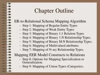
Chapter Outline. ER-to-Relational Schema Mapping Algorithm Step 1: Mapping of Regular Entity Types Step 2: Mapping of Weak Entity Types Step 3: Mapping of Binary 1:1 Relation Types Step 4: Mapping of Binary 1:N Relationship Types. Step 5: Mapping of Binary M:N Relationship Types.

E N D
Chapter Outline ER-to-Relational Schema Mapping Algorithm • Step 1: Mapping of Regular Entity Types • Step 2: Mapping of Weak Entity Types • Step 3: Mapping of Binary 1:1 Relation Types • Step 4: Mapping of Binary 1:N Relationship Types. • Step 5: Mapping of Binary M:N Relationship Types. • Step 6: Mapping of Multivalued attributes. • Step 7: Mapping of N-ary Relationship Types. Mapping EER Model Constructs to Relations • Step 8: Options for Mapping Specialization or Generalization. • Step 9: Mapping of Union Types (Categories).
The Mapping Algorithm • We have briefly discussed creating an ER diagram. • Creating the initial version is very much like creating a class diagram. • But mapping this to a schema follows a rigorous process, which can be described algorithmically.
Step 1: Mapping of Regular Entity Types • For each regular (strong) entity type E in the ER schema, create a relation R that includes all the simple attributes of E. • Choose one of the key attributes of E as the primary key for R. • If the key is composite, the set of simple attributes that form it will together form the primary key of R. • E.g.: Create relations EMPLOYEE, DEPARTMENT, and PROJECT in the schema corresponding to the entities in the ER diagram. SSN, DNUMBER, and PNUMBER are the primary keys for the relations EMPLOYEE, DEPARTMENT, and PROJECT as shown.
Step 2: Mapping of Weak Entity Types • For each weak entity type W in the ER schema with owner entity type E, create a relation R and include all simple attributes (or simple components of composite attributes) of W as attributes of R. • In addition, include as foreign key attributes of R the primary key attribute(s) of the relation(s) that correspond to the owner entity type(s). • The primary key of R is the combination of the primary key(s) of the owner(s) and the partial key of the weak entity type W, if any.
Step 2: Mapping of Weak Entity Types • E.g.: the relation DEPENDENT corresponds to the weak entity type DEPENDENT. The primary key SSN of the EMPLOYEE relation is a foreign key attribute of DEPENDENT (renamed to ESSN). • The primary key of the DEPENDENT relation is the combination {ESSN, DEPENDENT_NAME} because DEPENDENT_NAME is the partial key of DEPENDENT.
Step 3: Mapping of Binary 1:1 Relation Types – 1 • For each binary 1:1 relationship type R in the ER schema, identify the relations S and T that correspond to the entity types participating in R. There are three possible approaches: • Foreign Key approach: Choose one of the relations (S) and include as a foreign key in S the primary key of T. It is best to choose an entity type with total participation in R in the role of S. • Example: 1:1 relation MANAGES is mapped by choosing the participating entity type DEPARTMENT to serve in the role of S, because its participation in the MANAGES relationship type is total.
Step 3: Mapping of Binary 1:1 Relation Types – 2. • Merged relation option: An alternate mapping of a 1:1 relationship type is possible by merging the two entity types and the relationship into a single relation. This may be appropriate when both participations are total. • Cross-reference or relationship relation option: The third alternative is to set up a third relation R for the purpose of cross-referencing the primary keys of the two relations S and T representing the entity types.
Step 4: Mapping of Binary 1:N Relationship Types • For each regular binary 1:N relationship R, identify the relation S (the N-side of the relationship). • Include as foreign key in S the primary key of the relation T (the other entity participating in R). • Include any simple attributes of the 1:N relation type as attributes of S. • E.g.: 1:N relationship types WORKS_FOR, CONTROLS, and SUPERVISION in the schema. • For WORKS_FOR we include the primary key DNUMBER of the DEPARTMENT relation as foreign key in the EMPLOYEE relation (and call it DNO).
Step 5: Mapping of Binary M:N Relationship Types – 1 • For each regular binary M:N relationship type R, create a new relation S to represent R. • Include as foreign key attributes in S the primary keys of the relations that represent the participating entity types; their combination will form the primary key of S. • Also include any simple attributes of the M:N relationship type (or simple components of composite attributes) as attributes of S.
Step 5: Mapping of Binary M:N Relationship Types – 2. • E.g.: The M:N relationship type WORKS_ON from the ER diagram is mapped by creating a relation WORKS_ON in the relational database schema. • The primary keys of the PROJECT and EMPLOYEE relations are included as foreign keys in WORKS_ON (and renamed PNO and ESSN, respectively). • Attribute HOURS in WORKS_ON represents the HOURS attribute of the relation type. • The primary key of the WORKS_ON relation is the combination of the foreign key attributes {ESSN, PNO}.
Step 6: Mapping of Multivalued Attributes • For each multivalued attribute A, create a new relation R. This relation R will include an attribute corresponding to A, plus the primary key attribute K (as a foreign key in R) of the relation that represents the entity type of relationship type that has A as an attribute. • The primary key of R is the combination of A and K. If the multivalued attribute is composite, we include its simple components. • E.g.: The relation DEPT_LOCATIONS is created. The attribute DLOCATION represents the multivalued attribute LOCATIONS of DEPARTMENT, while DNUMBER (as foreign key) is the primary key of the DEPARTMENT relation. The primary key of R is the combination of {DNUMBER, DLOCATION}.
Step 7: Mapping of N-ary Relationship Types • For each n-ary relationship type R, where n>2, create a new relation S to represent R. • Include as foreign key attributes in S the primary keys of the relations that represent the participating entity types. • Also include any simple attributes of the n-ary relationship type (or simple components of composite attributes) as attributes of S.
The SUPPLY Ternary Relationship Type • E.g.: The relationship type SUPPLY can be mapped to a relation SUPPLY, whose primary key is the combination of the three foreign keys {SNAME, PARTNO, PROJNAME}
Mapping EER Model Constructs to Relations • Going beyond the ER model, we can extend the algorithm thus… • Step 8: Options for Mapping Specialization or Generalization. • Step 9: Mapping of Union Types (Categories)
Step 8: Options for Mapping Specialization or Generalization • Convert each specialization with m subclasses {S1, S2,….,Sm} and superclass C, with attributes {k,a1,…an} and k is the (primary) key, into relational schemas using one of the four following options: • Option 8A: Multiple relations: Superclass and subclasses. Create a relation L for C with attributes Attrs(L) = {k,a1,…an} and PK(L) = k. Create a relation Li for each subclass Si, 1 < i < m, with the attributes Attrs(Li) = {k} U {attributes of Si} and PK(Li)=k. This option works for any specialization (total or partial, disjoint or overlapping). • Option 8B: Multiple relations: Subclass relations only Create a relation Li for each subclass Si, 1 < i < m, with the attributes Attr(Li) = {attributes of Si} U {k,a1…,an} and PK(Li) = k. This option only works for a specialization whose subclasses are total (every entity in the superclass must belong to (at least) one of the subclasses).
Mapping the EER Schema using Option 8B OwnerId Tonnage
Step 8: Options for Mapping Specialization or Generalization • Option 8C: Single relation with one type attribute. Create a single relation L with attributes Attrs(L) = {k,a1,…an} U {attributes of S1} U…U {attributes of Sm} U {t} and PK(L) = k. The attribute t is called a type (or discriminating) attribute that indicates the subclass to which each tuple belongs • Option 8D: Single relation with multiple type attributes. Create a single relation schema L with attributes Attrs(L) = {k,a1,…an} U {attributes of S1} …U {attributes of Sm} U {t1, t2,…,tm} and PK(L) = k. Each ti, 1 < I < m, is a Boolean type attribute indicating whether a tuple belongs to the subclass Si.
Step 9: Mapping of Union Types (Categories) • For mapping a category whose defining superclass have different keys, it is customary to specify a new key attribute, called a surrogate key, when creating a relation to correspond to the category. • In the example below we can create a relation OWNER to correspond to the OWNER category and include any attributes of the category in this relation. The primary key of the OWNER relation is the surrogate key, which we called OwnerId.
Mapping the EER categories (union types) to relations. OwnerId CYear
Exercise: Create the Schema Name Code Addr BranchNo Addr 1 N Branches Bank Bank-Branch 1 1 Accts Loans N AcctNo Balance LoanNo N Type Account Type Loan M M Amount A_C L_C SSN Name N N Address Customer Phone