Download
1 / 15
160 likes | 362 Vues
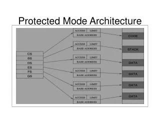
Venturing into protected-mode. Exploiting the x86 segment-registers’ hidden segment-descriptor cache to briefly enter and leave protected-mode. The system-segment registers. In protected-mode the CPU needs quick access to some important data-structures, such as: Memory-Segment Descriptors

E N D
Venturing into protected-mode Exploiting the x86 segment-registers’ hidden segment-descriptor cache to briefly enter and leave protected-mode
The system-segment registers • In protected-mode the CPU needs quick access to some important data-structures, such as: • Memory-Segment Descriptors • Interrupt-Gate Descriptors • Call-Gate Descriptors • Task-State Descriptors • Page-Directory and Page-Table Descriptors • Special CPU registers locate these items
GDT and IDT • The two most vital system registers for protected-mode execution are: • GDTR (Global Descriptor Table Register) • IDTR (Interrupt Descriptor Table Register) • Each of these is 48-bits wide and contains the base-address and segment-limit for an array of descriptors (the GDT and the IDT) • Special instructions allow access to these registers: SGDT/LGDT and SIDT/LIDT
48-bit Register-Format 47 16 15 0 Segment Base-Address Segment Limit 32 bits 16 bits
System Relationships Interrupt Descriptor Table descriptor Global Descriptor Table descriptor descriptor descriptor descriptor descriptor descriptor descriptor descriptor descriptor descriptor descriptor descriptor descriptor descriptor descriptor GDTR descriptor descriptor descriptor descriptor IDTR
LDT and TSS • For protected-mode multitasking, the CPU needs to access two other data-structures: • The current Local Descriptor Table (LDT) • The current Task-State Segment (TSS) • Again, special registers tell the CPU where to find these data-structures in memory (assuming protected-mode is enabled) • And special instructions afford access to them: SLDT/LLDT and STR/LTR
Indirection • Registers LDTR and TR are like segment-registers: they have a visible part (16-bits) and a “hidden” descroptor-cache part • The programmer-visible portion of these two registers holds a “segment-selector” (i.e., an array-index into the GDT array) • The hidden portion is updated from the GDT whenever these register get loaded
System Relationships Task State Segment Global Descriptor Table descriptor TR descriptor descriptor Local Descriptor Table descriptor descriptor descriptor descriptor descriptor descriptor descriptor descriptor descriptor descriptor descriptor descriptor descriptor LDTR descriptor descriptor GDTR
Reading LDTR and TR • The LDTR and TR registers are not able to be accessed while executing in real-mode • An “Undefined Opcode” exception (INT-6) will be generated if SLDT or STR opcodes are encountered in a “real-mode” program • So to obtain the values in these registers, any bootsector program must temporarily enable protected-mode
Control Register 0 • Register CR0 is the 32-bit version of the MSW register (Machine Status Word) • It contains the PE-bit (Protection Enabled) • when PE=0 the CPU is in real-mode • when PE=1 the CPU is in protected-mode P G C D N W A M W P N E E T T S E M M P P E Machine Status Word
Using the LMSW instruction • You can use the LMSW instruction to turn on the PE-bit (enables protected-mode) • But you cannot use LMSW to turn off PE (i.e., PE was a “sticky bit” in the 80286) • The Intel 80386 processor introduced a new name and enlarged size for the MSW • Special version of the ‘MOV’ instruction can either enable or disable the PE-bit
How to enter protected-mode ; This instruction-sequence turns on PE-bit mov eax, cr0 bts eax, #0 mov cr0, eax ; Warning: you need to do this with interrupts ; temporarily disabled, since the real-mode ; Interrupt Vector Table won’t work any more
How to leave protected-mode ; This instruction-sequence turns off PE-bit mov eax, cr0 btr eax, #0 mov cr0, eax ; Warning: you need to make sure that all of ; the segment-registers have proper access- ; rights and segment-limits in their caches to ; work correctly when back in real-mode!
Unmodified segment-registers • If you can arrange for your program not to change any segment-registers while PE=1 then your code can safely enter and leave protected-mode without creating GDT/IDT • This means you will have to have to make sure no interrupts or exceptions can occur while the PE-bit is set for protected-mode • Can use cli and sti to control interrupts • Avoid exceptions by doing nothing illegal
In-class Exercise • The ‘sysregs.s’ bootsector demo-program displays the current value found in the two 48-bit system registers: GDTR and IDTR • Your job is to add modifications that demo • Modify the ‘sysregs.s’ bootsector program so it will display registers LDTR and TR in addition to displaying GDTR and IDTR • Can you enter and leave protected-mode without causing a system “crash”?