Download
1 / 52
810 likes | 1.81k Vues
MICROPROCESSOR AND INTERFACING. AUTHORS :RAMESH.S.GAONKAR BADRI RAM DOUGLAS.V.HALL LIU AND GIBSON. Syllabus of Microprocessor. Introduction to microprocessor Architecture and block diagram of microprocessor 8085 microprocesso 8237 DMA Controller

E N D
MICROPROCESSOR AND INTERFACING AUTHORS :RAMESH.S.GAONKAR BADRI RAM DOUGLAS.V.HALL LIU AND GIBSON
Syllabus of Microprocessor • Introduction to microprocessor • Architecture and block diagram of microprocessor • 8085 microprocesso • 8237 DMA Controller • 8255 Programmable peripheral interface device • 8254 programmable interval timer • 8259 programmable inttrupt controller • 8086 microprocessor
What is Microprocessor? A siliconchip that contains a CPU. In the world of personal computers, the terms microprocessor and CPU are used interchangeably. At the heart of all personal computers and most workstations sits a microprocessor. Microprocessors also control the logic of almost all digitaldevices, from clock radios to fuel-injection systems for automobiles
Microprocessor def.. Con.. • Microprocessor is a programmable device • It can be instructed to perform given tasks with in its capability. • The programmer selects instruction from the list and determines the sequence of execution for a given task. • It takes input from the input device and process the input as it behaves like a CPU and gives the output.
Microprocessor def.. Con.. • Microprocessor is a clock driven semiconductor device consisting of electronic logic circuits manufactured by using a LSI or VLSI technique. • Microprocessor can be divided into three segments • 1)ALU • 2)Register array • 3)Control unit
Block diagram of microprocessor Microprocessor As CPU OUTPUT INPUT MEMORY
Characterstics which differentiate microprocessors • Instruction set: The set of instructions that the microprocessor can execute. • bandwidth: The number of bits processed in a single instruction. • clock speed: Given in megahertz (MHz), the clock speed determines how many instructions per second the processor can execute.
Structure of microprocessor • Chip containing no. of elements for the processing purposes.
History of microprocessor • Intel's 4004 is considered the first microprocesor . • The 4004 was later followed in 1972 by the 8008, the world's first 8-bit microprocessor.
History of microprocessor…… • then is the 8080 microprocessor evolved in 1974. • Then comes 8085 that is the 8 bit microprocessor
Continued… • Often the processor is required to manage various different tasks that have to be scheduled somehow and must also deal with outside interrupt sources such as an alarm when something goes wrong. • Real-time systems are those in which timeliness is as important as the correctness of the outputs, although this does NOT mean that they have to be ?fast systems?. • A real-time system does not have to process data in microseconds to be considered real-time - it must simply have response times that are constrained and thus predictable.
Real life applications of microprocessor • Microprocessors are used to handle a set of tasks that control one or more external events or systems. • Microprocessors are typically used in either reactive or embedded systems. • Reactive systems are those that have an ongoing interaction with their environment - for example, a fire-control system that constantly reacts to buttons pressed by a pilot. • Embedded systems are those used to control specialized hardware in which the computer system is installed - for example, the microprocessor system used to control the fuel/air mixture in the carburetor of many automobiles. • In embedded systems the software system is completely encapsulated by the hardware that it controls.
Some questions • What is SSI,MSI and LSI? • What is difference between microprocessor, microcontroller and microcomputer? • What is a bit, byte, nibble and a word? • What is difference between compiler and interpreter? • What is instruction and mnemonic?
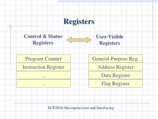
8085 programming model • Program counter • Stack pointer • General purpose registers • Accumulator • Flag registers • Data and address buses
8085 instruction set • Data transfer operations • Arithmetic operations • Logical operations • Branch operations • Machine control operations
Data transfer operations • MOV Rd,Rs • MVI R,8 bit • HLT • IN 8 bit port address accept the data from the input port specified in the second byte and loads into the accumulator. • NOP • OUT 8 bit port address copies the contents of the accumulator to the output port specified in the second byte,2 byte instruction
Data transfer operations • This group of instructions copies data from a location called a source to another a location called destination without modifying the contents of the source. • Data transfer can be between 1)registers • Specified data byte to a register or memory location • Between a memory location and a register
Addressing mode • Immediate addressing mvi • Register addressing mov • Direct addressing in/out ports • Indirect addressing
Logical operations • ANA R • ANI 8 bit • ORA R • ORI 8 bit • XRA R • XRI 8 bit • CMA
Arthimetic operations • ADD R • ADI 8 bit • SUB R • SUI 8 bit • INR R • DCR R
Branch operations • JMP 16 bit 2nd(low) and 3rd(high) byte specifies 16 bit • Memory address • JC • JNC • JZ • JNZ • JP • JM
Microprocessor architecture • The process of data manipulation and communication is determined by the logic design of the microprocessor called the arcitecture.
Microprocessor architecture • Microprocessor initiated operations • Internal operations Externally initiated operations To perform these functions microprocessor requires a group of logic circuits and set of signals called control signals.
Microprocessor initiated operations • Memory read • Memory write • I/O read • I/O write
Internal operations • Store 8-bit data • Perform arthimetic and logical operations • Test for conditions • Sequence the excuetion of operations • Store data temporarily during excuetion
8085 pin diagram Is 8 bit microprocessor, capable of addressing 64k of memory Has 40 pins ,operate with 3mhz single phase clock Require +5v of single power supply
8085 pin diagram Is 8 bit microprocessor, capable of addressing 64k of memory Has 40 pins ,operate with 3mhz single phase clock Require +5v of single power supply
Pin diagram conti…. • All the signals are classified into 6 groups • Address bus • Data bus • Control and status signals • Power supply and frequency signals • Externally initiated signals • Serial input output ports
Block diagram of 8085 microprocessor • It includes • Arithmetic and logic unit • Timing and control unit • Instruction register and decoder • Register array • Interrupt control • Serial input output control
8085 interrupt • What is interrupt? • Vectored interrupt • Non vectored interrupt • Enable and disable interrupt instructions • Pending interrupts
8085 interrupt • Interrupt is a process where an external device can get the attention of the microprocessor. • The process starts from the I/O device • The process is asynchronous. • Classification of Interrupts • Interrupts can be classified into two types: • Maskable Interrupts(Can be delayed or Rejected) • Non-Maskable Interrupts (Can not be delayed or Rejected) • Interrupts can also be classified into: • Vectored (the address of the service routine is hard-wired) • Non-vectored (the address of the service routine needs to be supplied externally by the device)
Interrupts • An interrupt is considered to be an emergency signal that may be serviced. • The Microprocessor may respond to it as soon as possible. • What happens when MP is interrupted ? • When the Microprocessor receives an interrupt signal, it suspends the currently executing program and jumps to an Interrupt Service Routine (ISR) to respond to the incoming interrupt. • Each interrupt will most probably have its own ISR.
Interrupts • When a device interrupts, it actually wants the MP to give a service which is equivalent to asking the MP to call a subroutine. This subroutine is called ISR (Interrupt Service Routine) • The ‘EI’ instruction is a one byte instruction and is used to Enable the non-maskable interrupts. • The ‘DI’ instruction is a one byte instruction and is used to Disable the non-maskable interrupts. • The 8085 has a single Non-Maskable interrupt. • The non-maskable interrupt is notaffected by the value of the Interrupt Enable flip flop.
8085 intrrupts • TRAP • RST7.5 • RST6.5 • RST 5.5 • INTR • INTA
Interrupt Vectors and the Vector Table • An interrupt vector is a pointer to where the ISR is stored in memory. • All interrupts (vectored or otherwise) are mapped onto a memory area called the Interrupt Vector Table (IVT). • The IVT is usually located in memory page 00 (0000H - 00FFH). • The purpose of the IVT is to hold the vectors that redirect the microprocessor to the right place when an interrupt arrives.
8255A Programmable peripheral interface • 8254 programmable interval timer • 8259 Programmable interval timer • 8237 DMA Controller
8255 Programmable peripheral interface • It can be programmed to transfer data under various conditions. • It has 24 I/O pins. • The function of 8255A classified acc to two modes. • A) BSR mode • I/O mode
8255 Programmable peripheral interface • Block diagram of 8255A • Control word • BSR mode • Mode 0 • Mode 1 • Mode 2
Control Word • D7 D6 D5 D4 D3 D2 D1 D0 0/1 BSR Mode I/O Mode For port C Mode0 Mode 1 Mode2 No effect on mode Simple I/O Handshake I/O for ports for ports A and or B A,B,C • Port C bits
8237 DMA Controller • DMA is an input output technique used for high speed data transfer • Data transfer between system memory and floppy disk • It introduces two new signals that are • HOLD • HLDA
DMA Controller cont…. • DMA Controller consists of • DMA channels and interfacing • DMA Signals • System interface • Programming the 8237 • DMA Execution consists of • Master and slave mode
8086 microprocessor • It is 16 bit microprocessor. • Contains 29000 transistors and is fabricated using HMOS technology. • Has addressing capacity of I megabyte. • Has 20 address pins. • +5v supply voltage
8086 Arcitecture • Internal registers • Control logic • Instruction queue • ALU • PSW • Pointers • Segment registers
8086 effective address computations • To provide flexible base addressing and indexing a data address may be formed by addressing together a combination of the BX or BP register contents SI or DI contents and a displacement.The result of such and address computation is called effective address.
8086 memory segmentation • Address within segments • Overlapping segments