Download
1 / 16
160 likes | 393 Vues
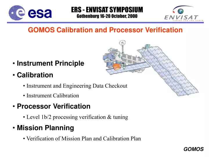
GOMOS Calibration and Processor Verification. Instrument Principle Calibration Instrument and Engineering Data Checkout Instrument Calibration Processor Verification Level 1b/2 processing verification & tuning Mission Planning Verification of Mission Plan and Calibration Plan.

E N D
GOMOS Calibration and Processor Verification • Instrument Principle • Calibration • Instrument and Engineering Data Checkout • Instrument Calibration • Processor Verification • Level 1b/2 processing verification & tuning • Mission Planning • Verification of Mission Plan and Calibration Plan
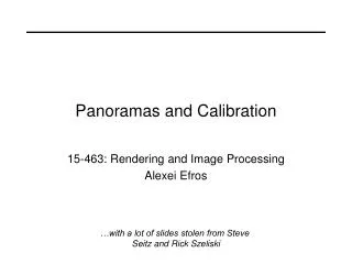
F(zi) Intensity F(zi) T(zi) = Intensity Fo Transmission Wavelength Wavelength Wavelength Intensity Wavelength Instrument Measurement Principle Fo F(z1) Fo 60 Km z 40 Km F(z) 20 Km Independent of gain drift
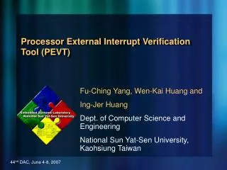
Intensity Wavelength Slit/Baffle y x Star Tracker Image 2 Depointing [mrad] 200 400 100 300 Time [msec] Instrument Measurement Principle As far as the star spectrum is concerned, GOMOS is a slit-less spectrometer, meaning that a movement of the point-like star target results in a spectral and spatial shift on the focal plane. To characterise such movements, the instrument star-tracker continuously samples the star image position. This information is then used in the ground processing to accurately align the individual spectra. Tracking Data Facilitates Depointing/Spectral Correction
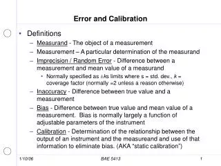
Oct Nov Dec Jan Feb Mar Apr May June L+ 3.5 month = Instrument Calibrated SODAP Health check Signal level and band setting Tracking capability Performance evaluation CALEX Verification Calibration First in-flight calibration Second in-flight calibration and Trend Analyis Definition of routine calibration opeations Schedule and obs plan for in-flight calibration Level 1b Processing chain verification (prototype) Level 1b Processing Tuning (prototype) L1b Processor verification Level 1b Processing Tuning (PDS) Level 1b chain Update (PDS) Launch Level 1b product coherency Val of geoloc & atm prods Schedule - Calibration & Processing Verification
On-Ground Processing Datation Geolocation Transmission spectra Wavelength Assignment Sample corrections Spectral Inversion Calibration Inputs Cross Section Computation Background Processing Smoothing Background Removal Vertical Inversion Covariance Processing Transmission Processing Level 2 Products Level 1b Processing Level 2 Processing
Calibration Needs Main parameters to be re-characterised during the commissioning phase: Correction functions Parameter (for in-orbit calibration) Comment / required accuracy Bad pixel processing Dark Signal Non-Uniformity Median filter Cosmic ray processing Threshold value Median filter Digital to electron conversion Sensitivity [LSB / radiometric unit] Monitoring of drift Non-linearity< 0.1 % Electronic chain offset< 1 % Dark Charge Removal Dark Signal Non-Uniformity < 1% Mirror reflectivity correction SFM Reflectivity Calibrated on-ground; 0.05%/deg Star background estimation Pixel-Response Non-Uniformity < 1 % IR Vignetting < 5% Slit transmission Star signal estimation Pixel-Response Non-Uniformity < 1 % IR Vignetting < 5 % Wavelength Assignment Wavelength Assignement 1/3 pixel Dispersion [nm/column] Level 2 processing Line Spread Function 5 % Only a very limited number of parameters are expected to change (red) and thus requires recalibration
Instrument Calibration Support Modes Besides the normal occultation mode, GOMOS has four other operation modes useful for calibration purposes. All modes will be fully exploited for calibration. • The linearity mode is the same as the occultation mode except that the integration time can be programmed from 0.25 to 10 second in steps of 0.25 second. • The uniformity mode produces pixel images of both spectrometer, photometer and SATU1 sensors. In this mode the instrument operates in open loop (no active tracking of stars, only orbit compensation). • The Spatial Spread Mode produces, as in uniformity mode, pixel images of spectrometers, photometers and SATU’s. The difference is that the mode operates in closed loop with the tracking chain and hence needs a star target to track.. • The Fictive Star Modeis similar to the occultation mode (same data format) except that there is no active tracking (the star is specified with a specific position and speed) SATU= Star Acquisition and Tracking Unit
Calibration Preparation The following resources and tools are prepared, to support the GOMOS commissioning activity: STARSEL- GOMOS star observation mission tool. GOSS - GOMOS system simulator. Includes atmospheric and instrument model to generate real GOMOS source packet products (measurement data). CALEX - GOMOS Calibration Processor. This software is installed and operated within the Instrument Engineering Calibration Processor. The main product is the GOMOS calibration database; used as input to the GOMOS geophysical product processor. GOPR- GOMOS level 1b (calibration and transmission spectra processing) and level-2 (geophysical processing) prototype. This processor generates exactly the same products as the PDS one and is used as reference processor. Various other analysis tools (specific tools, Excel and IDL routines etc..) PDS = Payload Data Segment (geophysical processor in ESRIN)
Level 1b verification and validation • Level 1b processing chain verification (step by step) :implementation of calibration and characterisation parameters. • Verification of data coherency (range) : Check the range of each level 1bproduct items. Analyse the self coherency of GOMOS products (e.g. level 2 products from same geolocation but observed with two different stars) • Validation of stellar derived products : Analyse the stellar spectra products and create a stellar spectra database • Data flagging monitoring and statistics : Monitor the data flagging of level 1b and limb products (quality flags) • Recommendations for routine observation plan : Provide inputs to the observation plan derived from level 1b product analysis • Update of level 1b processor
Level 2 Processing Verification • Level 2 processing chain verification (step by step) :Check functionality of the level 2 processing chain using real measurements • Coherency with model - climatology verification : Verification of the coherency using forward models (real star spectra, climatology models) • Tuning of Level 2 processing parameters :analyse and validate the level 2 products tuning of the parameters of the level 2 processing chain to identify the new initial operational configuration (iterative tuning). • Tuning of the Level 2 processor :modify, adjust the algorithms of the level 2 processing chain as appropriate. • Upgrade of the level 2 operational processor :implementation of the level 2 processing chain updates into the PDS operational chain.
Supporting Facilities and Interfaces FOS Flight Operation Segment PDS Processing Data Segment IECF Instrument Engineering Calibration Facility Data / Processing Config Observation commanding GOMOS Commissioning Centre Processor update RGT Reference Operation Plan Generation Tool Observation planning Products AO Groups External Scientific Studies NILU Norwegian Institute for Air Research SODAP Switch-On & Data Acquisition Phase Group
Spectral Line Spread Function (LSF) The GOMOS Level-2 algorithm basically consist of correlating a measured spectrum by a synthesised one; generated from the cross sections. A condition for this correlation is that the two spectra has the same resolution. As the instrument sets the limit, the synthesized one must first be convoluted with the instrument spectral LSF. The instrument LSF will be assessed in-orbit by observing narrow stellar lines (preferrably emission lines). The on-ground measurement is not expected to have changed (major contributing effects are defocus) and will be used.
Star Light Photo 1/2 IR1/2 Pointing Steering Front Mechanism UV VIS TEL SDE ICU MDE Satellite Data-bus GOMOS Functional Layout