Download
1 / 15
190 likes | 316 Vues
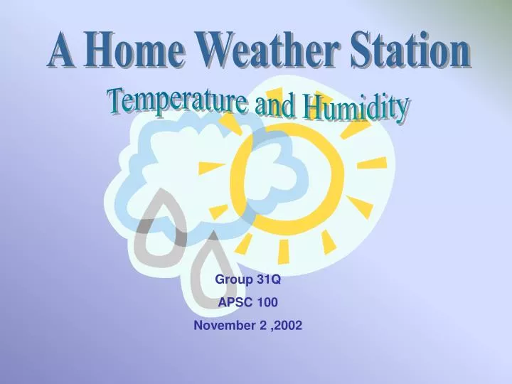
A Home Weather Station. Temperature and Humidity. Group 31Q APSC 100 November 2 ,2002. Team Members. Humidity Team Billy Smith Jacob Black Temperature Team George McDonald Keith Brown Supervised by… Dr. Geoff Lockwood Project Manager Bob. Presentation Overview. What We Learned

E N D
A Home Weather Station Temperature and Humidity Group 31Q APSC 100 November 2 ,2002
Team Members Humidity Team • Billy Smith • Jacob Black Temperature Team • George McDonald • Keith Brown Supervised by… • Dr. Geoff Lockwood • Project Manager Bob
Presentation Overview • What We Learned • Our Goal • Preliminary Design • Components • Progress Report
What We Learned • Tutorial 1: • How to construct circuits using bread-boards • How to measure voltage, current, and resistance (i.e. Resistance in parallel is R=1/R1 + 1/R2 + …1/Rn) • Tutorial 2: • Learned about operational amplifiers so that we can now add, subtract, integrate, and take the square root of the signal • Tutorial 3: • Gained Experience using an analog to digital converter and seven segment displays (i.e. Binary “1001” = Digital “9”)
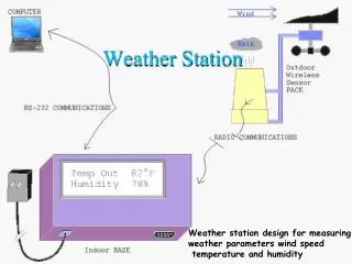
Our Goal • Learn to build and analyze simple circuits • Produce an inexpnsive (<$200) weather station suitable for home use • Temperature Range will be –40 O C to 40 O C with accuracy within a degree • Humidity will range from 0% to 100% with accuracy within 2%
Preliminary Design Proposed Complete Circuit • LM555 Timer/Square Wave Clock • AD7819 Analog to Digital Converter • Temperature Transducer Circuit • Humidity Transducer Circuit
Components • LM555 Timer/Square Wave Clock • AD7819 Analog to Digital Converter • Temperature Transducer Circuit • Humidity Transducer Circuit
1) LM555 Timer/Square Wave Clock • Used to generate a square root wave • Sends an analog “clock” signal to the AD converter • Square root wave produces intervals of reading and sampling of the analog input signal
2) Analog to Digital Converter (AD) Using an AD789 linked with the DM9368 common cathode display driver and a seven segment display we can: • Convert analog signal from transducers to a binary code • Convert binary code into a digital display (i.e. Temperature, Humidity, Wind Speed, and Pressure)
3) Temperature Transducer Circuit • LM35 precision integrated-circuit temperature sensor • 0.5°C accuracy guaranteeed (at +25°C) • Rated for full -55° to +150°C range
Minimum Supply Voltage vs. Temperature • Given temperature range produces a signal within 1v • An amplifier may be required
4) Humidity Transducer Circuit • HIH-3605-A transducer circuit allows us to read the relative humidity • Send an analog signal to the AD (Analog/Digital Circuit) converter
Output Voltage vs. Relative Humidity • Transducer outputs within target range of AD Converter
As a Final Progress Report • The Clock and the Analg / Digital Converter have been constructod and vigorosly tested • Next step will be two implement the temperatore • and humidity transducers • The group has been co-operating well due in no small part to the excellent Project managers