Download
1 / 48
1.07k likes | 2.7k Vues
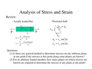
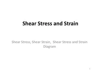
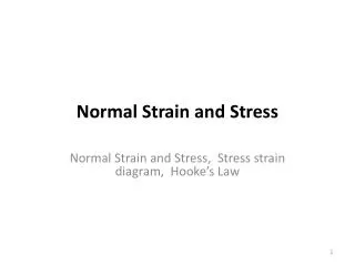
Stress-Strain Relationships. Stress is a measure of the force per unit area Strain is a measure of the unit change in length ( uniaxial stress) or angle (shear) Elastic deformation relates the stress to strain through the proportionality constant of the elastic modulus, E

E N D
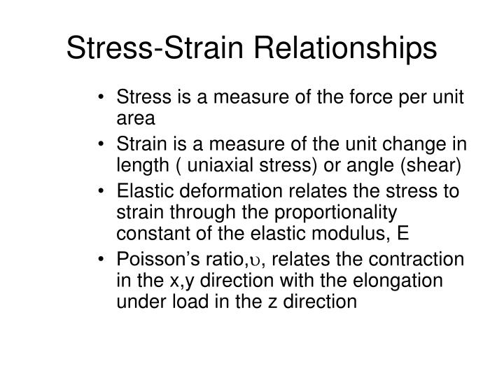
Stress-Strain Relationships • Stress is a measure of the force per unit area • Strain is a measure of the unit change in length ( uniaxial stress) or angle (shear) • Elastic deformation relates the stress to strain through the proportionality constant of the elastic modulus, E • Poisson’s ratio,, relates the contraction in the x,y direction with the elongation under load in the z direction
Relations of Stress-Strain A) Uniaxial tension B) Compression C) Shear A B D) Torsion D C D
Mechanical Materials Properties • Elastic Modulus- determines the elastic response of a material following Hooke’s law. Determines by uniaxial tensile testing, acoustic transmission, and vibrational response • Yield Point and Ultimate Tensile Strength ( UTS)- yield point determines the onset of plastic deformation as determined by a strain offset( usually .2%), while UTS determines the maximum strength • Coefficient of Thermal Expansion- measures the expansion over temperature, usually in microinches/in/oC. Thermally induced strains occur due to the mismatch between dissimilar materials. Measured with a dilatometer
Typical Stress-Strain Behavior Y.P. M = Ultimate Tensile Strenght Y.P. = Yield Point
Poisson’s Ratio =- x / z
Stress-Strain Distribution in an Adhesively Bonded Joint Typical variations of shear and peelstresses in a single lap joint for an adhesively bonded joint.Note that the shear stress is non- zero at the ends.
Fatigue Materials will fail at a lower lever than the UTS when subjected to cyclic loading. This is known as fatigue. The loading can be stress induced (mechanical loading) or stain induced (thermal cycling)
A ... p Nr = - 11 ,5"y) f e -- kT@,,@ A ... p Nr = - 11 ,5"y) f e -- kT@,,@ =(A\Illf,,e_ P A,y) kT@,,@ Thermal Cycle Fatigue The equation that describes most metals stresses repeatedly in uniaxial tension is the Coofin-Manson equation. The generalized equation,where Nf is the number of cycles to failure, f is the cyclic frequency, is the plastic strain and the other letters are constants is : For Pb-Sn solders, Engelmaier developed the following model
Temperature Effects Many mechanical properties are temperature dependent. For many of thelow melting point joining materials, the mechanical properties are a “mixture” of the high and low tem- perature properties
Creep Response • Steady state strain rate can be expressed as a function of the applied stress, testing temperature and microstructure • This is known as the power law and most metals exhibit power law creep behavior.
Phase Diagrams • Phase diagrams indicate structure and interactions between metals and/or ceramics • Eutectic - lowest melting point at eutectic composition. Transforms from a sold to liquid at eutectic temperature. Structure is a two phase lamella structure • Solid solution- a continuos “mixing” over all compositions. Structure is single phase • Intermetallic- unique phase at intermediate compositions, usually electronic phase such as AB, A2B,A2B3. Structure is often ordered
Kinetics of Transformation time 0
Phase Diagrams • Intermetallics typically are detrimental, especially if they exhibit limited solid solubility. Due to ordered structure, they tend to be brittle • Phase diagrams indicate relative growth of intermetallics between two metals and can estimate growth kinetics • Eutectic and solid solution reactions are most common in engineering applications
Common Phase Diagrams in Packaging • Eutectics in Pb-Sn,Sn-Bi,Sn-Ag,Pb-Sb,Ag-Cu • Complex intermetallics in Cu-Sn,Au-Sn,Al-Au and Au-Pb • Melting point of intermetallic indicated relative growth kinetics( Cu3Sn will grow faster than Cu6Sn5 • Intermetallics will grow and can consume parent material ( lower free energy of intermetallic
Intermetallic Formation A AB B
Strength Decrease with Intermetallic Growth Growth of intermetallics can decrease overall strength and especially thermal shock sensitivity. Intermetallics can be strong but have no ductility and toughness
Effect of Prolonged Thermal Exposure on Pb-Sn Solders Regular heating Prolonged Thermal Exposure
Alloying • Alloying changes many physical properties. Solid solution additions increase mechanical strength, raise resistivity and change the chemical potential • Solid solution alloying can change solderability and leach resistance (example Pd in Ag) • Alloying can decrease interdiffusion (example- Si additions to Al in IC metallization
Solder Failure Processes • Inferior mechanical strengths • Creep • Mechanical fatigue • Thermal fatigue • Thermal expansion anisotropy • Corrosion induced fatigue • Intermetallic compound formation • Detrimental microstructure development • Voids • Leaching • Gold Embrittlement
Aging of Au Embrittled Joint 51 micro in Au, unaged Ni3Sn4 Cu Ni AuSn4 200 hrs @ 150o C
Interface Failure Due to Au Embrittlement Interfacial failure between the Ni3Sn4 and AuSn4
Intermetallic Formation • Compatibility of solder composition to substrate • Length of soldering cycle • Temperature of soldering • Post solder storage conditions • Service conditions