Download
1 / 86
940 likes | 1.37k Vues
Introduction to Database Design Methodology. Chapter 5 Logical Database Design. Learning Goals. To describe database structure in terms of database schema To know the representation of relationships in relational database To transform ER diagram to database schema in relational database.

E N D
Introduction to Database Design Methodology Chapter 5 Logical Database Design
Learning Goals • To describe database structure in terms of database schema • To know the representation of relationships in relational database • To transform ER diagram to database schema in relational database
Table of Contents • Logical design in relational database • Transforming ER diagram to relational database schema • Transforming entity set and attributes • Representing relationship between tables • Transforming 1-to-1 relationship • Transforming 1-to-M relationship • Transforming M-to-N relationship
Logical Design in Relational Database
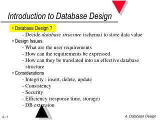
Logical Database Design • In relational database, data are stored in table(s). • Logical design in relational database is the design of table structures in database. • It is the step following the conceptual design of database. • Our goal is to transform the ER diagram in conceptual design into table structures in relational database.
All users’ requirements Conceptual Database Design Logical Database Design Database Logical Database Design
stud_id name dob sex STUDENT Relational Database Schema • The structure of a relational database is also called the relational database schema. • The table structure / schema is usually represented in the following ways: • For example, for the table STUDENT: The schema is represented as STUDENT (stud_id, name, dob, sex) OR
Relational Database Schema Note: • The primary key is underlined. • For simplicity, we have not listed out the data type of each field in representing the table structure. • A more detailed representation including the data type of each field is: STUDENT ( stud_id:char(5), name:char(20), dob:date, sex:char(1) )
Transforming ER Diagram to Relational Database Schema
ER Diagram and Relational Database • Corresponding items in entity-relationship diagram and relational database:
ER Diagram and Relational Database Entity Set Attribute Attribute value stud_id = “s0012” name = “Chan Tai Man” dob = #1997/1/1# sex = “M” Entity Attribute Attribute value stud_id = “s0022” name = “Wong May May” dob = #1998/2/5# sex = “F” table fields record
Transforming Entity Set and Attributes
name dob stud_id sex STUDENT stud_id name dob sex STUDENT Transforming Entity Set and Attributes Example ER Diagram: Schema: STUDENT (stud_id, name, dob, sex) OR
Activity 1 Task 1
book_title author book_id publisher BOOK name major teach_id sex TEACHER Task 1 Construct the table schemas for the following two entities
Representing Relationship between Tables
Relationship Entity Entity Transforming Relationships • How to transform relationships in ER diagram into relational database schema? • To answer this question, we should first understand how to represent relationship between tables in relational database. • The idea of representing relationship between tables is just similar to the case of designing “matching” exercises. ?
Activity 1 Task 2
Suppose we want to design an exercise on “matching” the items on the left-hand-side to the corresponding items on the right-hand-side. How to represent the matching/association between items? Task 2
Task 2 Method 1: Joining items by lines. Please try.
Task 2 Method 2: Fill in the blanks on the left table. Please try.
Task 2 Method 3: Fill in the blanks on the right table. Please try.
Task 2 Method 4: Fill in the blanks on the “middle” table. Please try.
Representing Relationship between Tables In the above discussion, • Method 1 is just the graphical representation of relationship between tables.
Representing Relationship between Tables • In Method 2,the relationship is set up by adding a column of primary key of the right table to the left table. We call this new field the foreign key of the left table. • A foreign key is a field (or a composite of fields) in one table that matches a primary key (may be composite) in another table. • Relationship between tables is set up by relating the foreign key in one table to the primary key in the other table. foreign key
Representing Relationship between Tables • Method 3 is just similar to Method 2. This time, the primary key of the left table is added to the right table as foreign key. foreign key
Representing Relationship between Tables • In Method 4, a new table is created with the columns of primary keys from the other two tables as foreign keys.
Transforming Relationships • Depending on the different types of binary relationships in ER diagram, there are different methods to transform the relationships into the corresponding table structures. • The basic approach is to add appropriate foreign key(s) in appropriate table. The relationships between tables are set up by relating the foreign key in one table to the primary key in the other table. • The transformation methods can be classified into the following cases: • Transforming 1-to-1 binary relationship • Transforming 1-to-M binary relationship • Transforming M-to-N binary relationship
Transforming 1-to-1 Relationship
1 1 Relationship A B Transforming 1-to-1 Relationship Given a one-to-one binary relationship between two entity sets A and B. Steps: • Construct table schemas of the two entity sets. • Choose one of entity set, say A. • If possible, choose the one in which each entity must be associated with one entity in the other entity set. • Add the primary key from the other schema (B) as a foreign key in schema of A. • Include the attribute(s) (if any) of the relationship as attribute(s) of schema of A.
club_id club_name name dob Leads 1 1 stud_id STUDENT CLUB sex Transforming 1-to-1 Relationship Example • Student leads club in a school Original tables: STUDENT CLUB
club_id club_name name dob Leads 1 1 STUDENT CLUB stud_id sex Transforming 1-to-1 Relationship Example (con’t) • 1. Construct table schemas of the two entity sets. • Schema: STUDENT (stud_id, name, dob, sex) • CLUB (club_id, club_name)
club_id club_name Leads 1 1 name dob STUDENT CLUB stud_id sex Transforming 1-to-1 Relationship Example (con’t) • Choose entity set (CLUB) in which each entity should be associated with one entity in the other entity set. Add the primary key from the other schema as a foreign key in this schema (CLUB). • Schema: STUDENT (stud_id, name, dob, sex) • CLUB (club_id, club_name,stud_id) foreign key
club_id club_name name dob Leads 1 1 STUDENT CLUB stud_id sex stud_id name dob sex STUDENT club_id club_name stud_id CLUB Transforming 1-to-1 Relationship Example (con’t) Schema (Graphically):
Transforming 1-to-1 Relationship Example (con’t) Schema: STUDENT (stud_id, name, dob, sex) CLUB (club_id, club_name,stud_id) Resulting tables: CLUB STUDENT primary key of CLUB primary key of STUDENT foreign key of CLUB
Leads 1 1 STUDENT CLUB Transforming 1-to-1 Relationship Discussion Compare the following two choices of adding foreign key. Which one is better?Explain briefly. Schema 1: STUDENT (stud_id, name, dob, sex) CLUB (club_id, club_name,stud_id) foreign key Schema 2: STUDENT (stud_id, name, dob, sex, club_id) CLUB (club_id, club_name)
Transforming 1-to-1 Relationship Discussion - Answer: Schema 1: STUDENT (stud_id, name, dob, sex) CLUB (club_id, club_name,stud_id) STUDENT CLUB • No null item in the foreign key field. • Each club must be led by one student
Transforming 1-to-1 Relationship Discussion - Answer (con’t): Schema 2: STUDENT (stud_id, name, dob, sex, club_id) CLUB (club_id, club_name) STUDENT CLUB • Some records have null values in the foreign key field. • Some students may not lead any club. Therefore, schema 1 is better (why?).
Activity 1 Task 3
A teacher may lead a class (as a form master). Transform the above ER diagram into database schema. sex class_id major 1 1 Leads teach_id CLASS TEACHER cls_name name Task 3
Transforming 1-to-M Relationship
Relationship 1 M A B Transforming 1-to-M Relationship Given a one-to-many binary relationship between two entity sets A and B. Steps: • Construct table schemas of the two entity sets A and B. • Add the primary key of A (the “one” side) as a foreign key of B (the “many” side). • Include the attribute(s) (if any) of the relationship as attribute(s) of B.
name dob stud_id class_id cls_name sex room 1 M Has STUDENT CLASS Transforming 1-to-M Relationship Example • A class has many students Original tables: STUDENT CLASS
name dob stud_id class_id cls_name sex room 1 M Has STUDENT CLASS Transforming 1-to-M Relationship Example (con’t) • 1. Construct table schemas of the two entity sets. • Schema: • CLASS (class_id, cls_name, room) • STUDENT (stud_id, name, dob, sex)
name dob stud_id class_id cls_name sex room 1 M Has STUDENT CLASS Transforming 1-to-M Relationship Example (con’t) • Add the primary key of CLASS as a foreign key in STUDENT. • Schema: • CLASS (class_id, cls_name, room) • STUDENT (stud_id, name, dob, sex, class_id) foreign key
name dob stud_id class_id cls_name sex room 1 M Has STUDENT CLASS stud_id name dob sex STUDENT class_id cls_name room CLASS class_id Transforming 1-to-M Relationship Example (con’t) Schema (Graphically):
Transforming 1-to-M Relationship Example (con’t) Schema: CLASS (class_id, cls_name, room) STUDENT (stud_id, name, dob, sex, class_id) Resulting tables: STUDENT CLASS primary key of STUDENT primary key of CLASS foreign key of STUDENT
Has M 1 CLASS STUDENT Transforming 1-to-M Relationship Discussion Compare the following two choices of adding foreign key. Which one is better?Explain briefly. Schema 1: CLASS (class_id, cls_name, room) STUDENT (stud_id, name, dob, sex, class_id) foreign key Schema 2: CLASS (class_id, cls_name, room, stud_id) STUDENT (stud_id, name, dob, sex)
Transforming 1-to-M Relationship Discussion - Answer Schema 1: CLASS (class_id, cls_name, room) STUDENT (stud_id, name, dob, sex, class_id) CLASS STUDENT No duplication of data, except the foreign key values.
Transforming 1-to-M Relationship Dissussion - Answer (Con’t) Schema 2: CLASS (class_id, cls_name, room, stud_id) STUDENT (stud_id, name, dob, sex) STUDENT CLASS • Some records with duplicate data in cls_name and room. • A class can contain many students Therefore, schema 1 is better (why?).