Download
1 / 20
200 likes | 370 Vues
AMS-02 Cryosystem. Phase III Flight Safety Review January 12, 2010 Phil Mott. AMS-02 Cryosystem. Vacuum Case Main Helium Tank Plumbing & Valves. Cryosystem Schematic. SUPER INSULATION & VAPOR COOLED SHIELDS. MAGNET RACETRACK COIL (DIPOLE COIL ROTATED 90 o ). SUPERFLUID HELIUM TANK.

E N D
AMS-02 Cryosystem Phase III Flight Safety Review January 12, 2010 Phil Mott
AMS-02 Cryosystem • Vacuum Case • Main Helium Tank • Plumbing & Valves
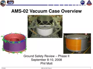
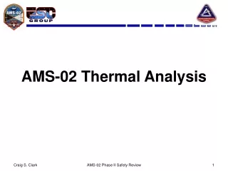
SUPER INSULATION & VAPOR COOLED SHIELDS MAGNET RACETRACK COIL (DIPOLE COIL ROTATED 90o) SUPERFLUID HELIUM TANK VACUUM SPACE 1 x 10⁻⁶ TORR SUPER INSULATION & VAPOR COOLED SHIELDS Vacuum Case OUTER JOINT • Vacuum jacket for the superconducting magnet • Inner Joint: • Welded U groove design • Outer Joint: • Bolted joint with double o-rings UPPER SUPPORT RING UPPER CONICAL FLANGE INNER JOINT INNER CYLINDER LOWER CONICAL FLANGE OUTER CYLINDER LOWER SUPPORT RING
Vacuum Case Certification • Helium Leak Tests • Both o-rings at all locations and both closeout welds were leak tested to show a better than 1.0 x 10⁻⁷ std cc/sec permeation • Proof Pressure Test: • The VC was successfully pressure tested to 1.8 atm absolute (1.0 x MDP) • Closeout Weld • Process certified to MSFC-SPEC-504C • Inspections • Visual • Dye Penetrant • Ultrasonic
Main Helium Tank • 2500 liter toroidal vessel which is constructed from Al 5083 • All welded structure • Helium Leak Test • Both halves leak tested along with full assembly • Proof Pressure Test • Successfully tested to 3.3 bar (MDP is 3.0) • Superfluid Helium Leak Test • Tank was leak checked after it was assembled inside of the VC due to issues with the ground testing rig. No leaks were found.
Burst Discs • Both the Vacuum Case and the main helium tank are protected by burst disc. These will be covered in detail in a later presentation.
Warm & Cold Valves • The system uses two sets of gas-actuated valves in order to move the liquid helium around the cryosystem. • The cold valves are located on the main helium tank • The warm valves are located on the VC • Actuation gas comes from the Warm Helium Supply on the VC.
Pilot Valve Vacuum Vessel (PVVV) • The PVVV contains the pilot valves that control the cold valves inside of the magnet. This prevents heat leak into the actuation lines. • System was installed in place, so a proof pressure test to 1.5xMDP cannot be done without risking damage to other components. Equivalent verifications being developed with EP. • Vacuum leak checked.
PVVV Changes • Design changed from an all welded configuration to a bolted o-ring seal (for valve replacement if necessary). Does not affect safety. • Line added to vent pump from PVVV to pump out helium from valve exhaust for a reduced heat load from L-88 to launch.
Warm Helium Supply • Provides helium that actuate both the warm and cold valves. • Covered in detail in a later presentation
Superfluid Cooling Loop (SCL) • The SCL is a closed system that is used to continually cool the magnet. • A serpentine tube is located inside of the main helium tank and the cooling loop is run along the top and bottom of the magnet coils. • The SCL is protected by a 20 bar burst disc that vents into the main helium tank. • Nominal operating pressure is 1 bar
Cool Down Circuit • Only used to initially cool down the magnet and after a quench to re-cool the magnet. • Tubes run along the top and bottom of the magnet coils and connected by thermal bus bars.
Current Leads • The current leads are used to charge the magnet and are cooled by flowing helium through the middle of the lead. • The current leads functioned nominally after the fix was implemented (covered in a separate presentation).
Thermo-mechanical Pump • The thermo-mechanical pump is used to pump helium from the main tank into the cryosystem during re-cooling of the magnet after a quench and during charging. • It has no moving parts and is actuated by a heater and primed by surface tension. • Both TMP’s function as designed.
Porous Plug & Nominal Venting • As helium in the main tank boils off, it is vented through a porous plug that separates the gas from the superfluid helium. • The vapor passes through the Vapor Cooled Shields, and then out through a port on the VC which then splits into three lines. • The first line goes to the flight vent, which is used on-orbit • The second line goes to a port with a connection to the CGSE pumps, which is used on the ground. • The third line goes to the On-Board Pump, which is used during transportation and in the payload bay.
Vapor Cooled Shields (VCS) • There are 4 VCS between the helium tank and the VC. As the helium boils off in the main helium tank, it flows through pipework attached to the 4 VCS’s that intercept incoming heat. • The VCS’s are constructed from strips of pure aluminum. • The VCS’s are separated by layers of superinsulation (aluminized Mylar and nylon netting)
VCS Supports • VCS 2 & 4 are supported by a carbon fiber honeycomb structure on the top and bottom. They are connected to each other by a series of wires.
Cryocoolers • Four Stirling-cycle cryocoolers used to remove additional heat from VCS 4 and reduce the external heat leak. • The cryocoolers were developed by Sunpower and modified by GSFC for flight. • Qualification cooler has been run for twice the nominal mission lifetime without incident.
Fill Port • The Fill Port is only used for ground operations during filling and topping off of the main helium tank.