Download
1 / 1
10 likes | 229 Vues
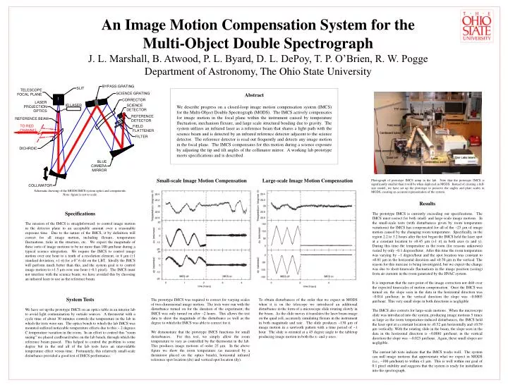
Small-scale Image Motion Compensation. Large-scale Image Motion Compensation.

E N D
Small-scale Image Motion Compensation Large-scale Image Motion Compensation Photograph of prototype IMCS setup in the lab. Note that the prototype IMCS is significantly smaller than it will be when deployed in MODS. Instead of creating a full-size model, we have set up the prototype to preserve the angles and plate scales in MODS, creating an accurate representation of the system. Schematic drawing of the MODS IMCS system optics and components. Note: figure is not to scale. The prototype IMCS was required to correct for varying scales of two-dimensional image motion. The tests were run with the disturbance turned on for the duration of the experiment; the IMCS was only turned on after ~2 hours. This allows the test data to show the magnitude of the disturbance as well as the degree to which the IMCS was able to correct for it. We demonstrate that the prototype IMCS functions for small disturbances. For this test, we simply allow the room temperature to vary as controlled by the thermostat in the lab. This produces image motions of order 25 μm. In the above figure we show the room temperature (as measured by a thermistor placed on the optics bench), horizontal infrared reference spot location (dx) and vertical spot location (dy). To obtain disturbances of the order that we expect in MODS when it is on the telescope we introduced an additional disturbance in the form of a microscope slide rotating slowly in the beam. As the slide moves it translates the laser beam image on the quad cell, accurately simulating flexure in the instrument in both magnitude and rate. The slide produces ~130 μm of image motion in a sawtooth pattern with a time period of ~1 hour. The slide is oriented at a 45 degree angle to the tabletop producing image motion in both the x- and y-axes. An Image Motion Compensation System for the Multi-Object Double Spectrograph J. L. Marshall, B. Atwood, P. L. Byard, D. L. DePoy, T. P. O’Brien, R. W. Pogge Department of Astronomy, The Ohio State University Abstract We describe progress on a closed-loop image motion compensation system (IMCS) for the Multi-Object Double Spectrograph (MODS). The IMCS actively compensates for image motion in the focal plane within the instrument caused by temperature fluctuation, mechanism flexure, and large scale structural bending due to gravity. The system utilizes an infrared laser as a reference beam that shares a light path with the science beam and is detected by an infrared reference detector adjacent to the science detector. The reference detector is read out frequently and detects any image motion in the focal plane. The IMCS compensates for this motion during a science exposure by adjusting the tip and tilt angles of the collimator mirror. A working lab prototype meets specifications and is described. Results The prototype IMCS is currently exceeding our specifications. The IMCS must correct for both small- and large-scale image motions. In the small-scale tests (with disturbances given by room temperature variations) the IMCS has compensated for all of the ~25 μm of image motion caused by the changing room temperature. Specifically, in the region 2.2 to 3.2 hours after the test began the IMCS held the laser spot at a constant location to ±0.45 μm (±1 σ) in both axes (x and y). During this time the temperature in the room (for reasons unknown) varied by only ~0.1 degrees/hour. After this time the room temperature was varying by ~1 degree/hour and the spot location was constant to ±0.81 μm in the horizontal direction and ±0.70 μm in the vertical. The reason for this increase is being investigated, but we expect the change was due to short-timescale fluctuations in the image position (seeing) from air currents in the room generated by the HVAC system. It is important that the zero point of the image correction not drift over the expected timescales of motion compensation. Once the IMCS was turned on, the slope seen in the data in the horizontal direction was ~0.014 μm/hour; in the vertical direction the slope was ~0.0005 μm/hour. This very small slope in both directions is negligible. The IMCS also corrects for large-scale motions. When the microscope slide was introduced into the system, producing image motions 5 times as large as the room temperature-induced disturbances, the IMCS held the laser spot at a constant location to ±0.52 μm horizontally and ±0.59 μm vertically. With the rotating slide in the beam, the slope seen in the data in the horizontal direction is ~0.0081 μm/hour; in the vertical direction the slope was ~-0.025 μm/hour. Again, these small slopes are negligible. The current lab tests indicate that the IMCS works well. The system can null image motions that approximate what we expect in MODS (i.e., ~100 μm/hour) to within <1 μm. This is well within our goal of 0.1 pixel stability and suggests that the system is ready for installation into the spectrograph. Specifications The mission of the IMCS is straightforward: to control image motion in the detector plane to an acceptable amount over a reasonable exposure time. Due to the nature of the IMCS, it by definition will correct for all image motion, including flexure, temperature fluctuations, ticks in the structure, etc. We expect the magnitude of these sorts of image motions to be no more than 100 μm/hour during a typical science integration. We require the IMCS to control image motion over one hour to a tenth of a resolution element, or 6 μm (±1 standard deviation; ±1 σ) for a 0”.6 slit on the LBT. Ideally the IMCS will perform much better than this, and the system goal is to control image motion to ±1.5 μm over one hour (~0.1 pixel). The IMCS must not interfere with the science beam; we have avoided this by choosing an infrared laser to use as the reference beam. System Tests We have set up the prototype IMCS on an optics table in an interior lab to avoid light contamination by outside sources. A thermostat with a cycle time of about 30 minutes controls the temperature in the lab in which the tests were run. The optics bench to which the lab IMCS was mounted suffered noticeable temperature effects due to this ~ 2 degrees C temperature variation in the room. In an effort to control this “room seeing” we placed cardboard tubes on the lab bench, through which the reference beam passed. This helped to control the problem to some degree but in the end all of the lab tests have an unavoidable temperature effect versus time. Fortunately, this relatively small-scale disturbance provided a good test of IMCS performance.