Download
1 / 24
250 likes | 397 Vues
H.-U. Auster, M. Mandea, A. Hemshorn , E. Pulz, M. Korte. An Automatic Instrument to Measure the Absolute Components of the Earth's Magnetic Field. Outline. Fundamentals of the Method Magnetic field along a rotation axis Elimination of systematic measurement errors

E N D
H.-U. Auster, M. Mandea, A. Hemshorn, E. Pulz, M. Korte An Automatic Instrument to Measure the Absolute Components of the Earth's Magnetic Field
Outline • Fundamentals of the Method • Magnetic field along a rotation axis • Elimination of systematic measurement errors • Manually performed test of the method in Niemegk • Automation • Magnetometers • Mechanics & Optics • Controlling • Set up in Belsk • Outlook
Motivation Manually performed absolute measurement in Hermanus by rotation of a fluxgate magnetometer about two well defined axes Ongoing activities to automate absolute measurement • Automating of DI-Flux • Manipulation of vector proton magnetometer • Automating of rotation of a vector fluxgate magnetometer about two well defined axes Auster H.U., V.Auster, A new method for performing an absolute measurement of the geomagnetic field, Meas. Sci. Technol. 14, 1013-1017, 2003
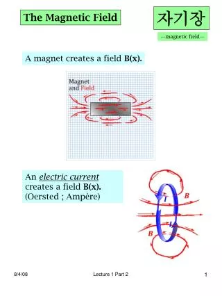
Magnetic field along a rotation axis (1) Co-ordinate systems • Red: arbitrary oriented fluxgate magnetometer • Black: Geophysical reference system • Relation between both: Euler angles Rotation about Precession angle ivariable • and constant • Bz = Bz(υ,φ)
Magnetic field along a rotation axis (2) Computation of field in rotation axis • Three independent measurements with arbitrary I necessary • Magnitude of B in direction of rotation axis becomes independent from sensor orientation angles and Matrix MB of measurement results Unit vector of sensor orientation
Measurement Procedure • Rotation A to adjust mechanical axis to azimuth marks • Rotation B to turn the sensor about the mechanical axes • Always 360° forward and backward • 6 measurement stops each rotation direction (B and azimuth) • Rotation C for magnetometer calibration y y x x Measurement time: 30 minutes
Elimination of systematic measurement errors • Magnetometer errors by scalar calibration • Rotation about two axes sufficient for full determination of linear transfer function (offsets, scale factors, non orthogonality) • Full Earth field magnetometer necessary, high requirements on linearity (10-5) • Orientation of rotation axes • Horizontal balance by level tube, misalignment of level tube eliminated by interchanging of its ends • Azimuth by telescope, misalignment of optical axis and rotation axis eliminated by rotation of telescope
Measurement Results of one year operation in Niemegk - Z Standard deviation: 1.0nT 2005 2006
Measurement Results of one year operation in Niemegk - D Standard deviation after trend and readjustment correction: 0.6nT 2005 2006
Measurement Results of one year operation in Niemegk - Magnetometer
Steps to automation • Magnetometers • Optical control • Mechanics: 3 Rotations • Rotation about measurement axis - arbitrary angles • Turn Table - arbitrary, but well known angle • Sensor rotation - arbitrary angle • Controlling • Hardware • Software
Magnetometers basket magnetometer • two digital 3-axes fluxgate magnetometers • range: 64000nT • resolution: 0.01nT • Non linearity < 10-5 • Serial & Flashcard interface • Proton-Magnetometer • Range: 20000-64000nT • resolution 0.01nT • Serial & Flashcard interface variometer scalar magnetometer
Performance of Magnetometers Variometer Basket magnetometer Observatory Data
Performance of Magnetometers Variometer - Obs Basket - Obs Variometer - Basket
Components of the optical system • Neodym Laser • Coupled in by fibre optics • PSD 2cm x 2cm • Resolution < 0.1 mm • Protected from stray light by • Band-filter (635nm) • Black tube • Azimuth Mark • Made by ceramics • Grounded in concrete Bild PSD
~ 15 m 0.2mm = atan(0.2mm/15 m) ~ 3'' Performance of optical system • Stability of azimuth mark: • Quarzgut 0.5 ppm/°C • Displacement < 0.1 mm (h=2m, T = 50°C)
Rotation A by Pneumatics • Pointing requirements: • 1cm/20m • 0.1mm/20cm • 2arcmin • Well defined end positions necessary • 7kg has to be rotated • Low friction by bearing • Importance of surface treatment • Pressure supply necessary (2 bar)
Rotation B & C by Piezo Motors Attempts to develop non magnetic motors for sensor rotation (1) Application example (2) Linear motor (3) Rotation to linear conversation (4) Final solution using gravitation
Control Unit • GPS controlled Timing • Motor control • rotation about measurement axis by piezo motor • Flip mechanism by piezo motor • Pneumatic control • Turn table rotation by two valves • Laser switching and PSD read out • Magnetometer control • Pre processing of data
Outlook • System has to run permanently in Niemegk • Reliability have to be tested and improved • Redesign of laser optics and some mechanical parts • Option: Replacement of pneumatics by Piezo motor driven system • New design for lower latitudes
Acknowledgement • GFZ for personal and financial investigation • All the the people designed and manufactured the mechanics (in Niemegk Potsdam Braunschweig Lindau and Garching) • Magson for magnetometers and software support • Belsk observatory for support to install the facility
Measurement Results of one year operation in Niemegk - H Standard deviation: 1.4nT