Download
1 / 51
680 likes | 1.12k Vues
LAN Technologies. Chapter 05. Introduction. A local area network (LAN) is a group of

E N D
LAN Technologies Chapter 05
Introduction • A local area network (LAN) is a group of computers and associated devices that share a common communications line or wireless link. Typically, connected devices share the resources of a single processor or server within a small geographic area (for example, within an office building).Usually, the server has applications and data storage that are shared in common by multiple computer users in LAN.
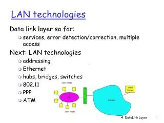
LAN technologies Data link layer so far: • services, error detection/correction, multiple access Next: LAN technologies • addressing • Ethernet • hubs, bridges, switches • 802.11
Ethernet • Ethernet is the most widely-installed local area network ( LAN) technology. • An Ethernet LAN typically uses coaxial cable orspecial grades of twisted pair wires. Ethernet is also used in wireless.A basic hard-wired LAN consists of the following components: - Two or more computers to be linked together, or networked. - A network interface card (NIC) in each computer. -Ethernet cable to connect to each computer. A networking switch or networking hub to direct network traffic. Networking software.
Ethernet MAC Ethernet Address • – End nodesareidentified by theirEthernet Addresses (MAC Address or Hardware Address) which is a unique 6 Byte address. MAC Address is represented in Hexa Decimal format e.g 00:05:5D:FE:10:0A The first 3 bytes identify a vendor (also called prefix) and the last 3 bytes are unique for every host or device – –
Ethernet MAC The IEEE 802.3 Ethernet and 802.5 Token Ring protocols specify that the MAC sub-layer must supply a 48-bit (6 byte) address. • • The first 3 byte Serial Number. is thevendorcode andother3 byte is • MACAddressis assignedto NIC whenthe factory manufacturesthecardandit wasstored in aROM of NIC(NetworkInterfaceCardor NetworkCard)
LAN Addresses andAddress Resolution Protocol(ARP) 32-bit IP address: • network-layer address, hierarchical • used to get datagram to destination IP network (recall IP network definition) LAN (or MAC or physical or Ethernet) address: • used to get datagram from one interface to another physically-connected interface (same network) • 48 bit MAC address (for most LANs) burned in the adapter ROM, flat address
LAN Addresses and ARP Each adapter on LAN has unique LAN address
LAN Address (more) • MAC address allocation administered by IEEE • manufacturer buys portion of MAC address space (to assure uniqueness) • Analogy: (a) MAC address: like Social Security Number (b) IP address: like postal address • MAC flat address => portability • can move LAN card from one LAN to another • IP hierarchical address NOT portable • depends on IP network to which node is attached
223.1.1.1 223.1.2.1 E B A 223.1.1.2 223.1.2.9 223.1.1.4 223.1.2.2 223.1.3.27 223.1.1.3 223.1.3.2 223.1.3.1 Recall earlier routing discussion Starting at A, given IP datagram addressed to B: • look up net. address of B, find B on same net. as A • link layer send datagram to B inside link-layer frame frame source, dest address datagram source, dest address A’s IP addr B’s IP addr B’s MAC addr A’s MAC addr IP payload datagram frame
Question: how to determine MAC address of B knowing B’s IP address? ARP: Address Resolution Protocol • Each IP node (Host, Router) on LAN has ARP table • ARP Table: IP/MAC address mappings for some LAN nodes < IP address; MAC address; TTL> • TTL (Time To Live): time after which address mapping will be forgotten (typically 20 min)
A wants to send datagram to B, and A knows B’s IP address. Suppose B’s MAC address is not in A’s ARP table. A broadcasts ARP query packet, containing B's IP address all machines on LAN receive ARP query B receives ARP packet, replies to A with its (B's) MAC address frame sent to A’s MAC address (unicast) A caches (saves) IP-to-MAC address pair in its ARP table until information becomes old (times out) soft state: information that times out (goes away) unless refreshed ARP is “plug-and-play”: nodes create their ARP tables without intervention from net administrator ARP protocol
Routing to another LAN walkthrough: send datagram from A to B via R assume A know’s B IP address • Two ARP tables in router R, one for each IP network (LAN) • In routing table at source Host, find router 111.111.111.110 • In ARP table at source, find MAC address E6-E9-00-17-BB-4B, etc A R B
A creates datagram with source A, destination B • A uses ARP to get R’s MAC address for 111.111.111.110 • A creates link-layer frame with R's MAC address as dest, frame contains A-to-B IP datagram • A’s data link layer sends frame • R’s data link layer receives frame • R removes IP datagram from Ethernet frame, sees its destined to B • R uses ARP to get B’s physical layer address • R creates frame containing A-to-B IP datagram sends to B A R B
Ethernet Frame Structure Sending adapter encapsulates IP datagram (or other network layer protocol packet) in Ethernet frame Preamble: • 7 bytes with pattern 10101010 followed by one byte with pattern 10101011 • used to synchronize receiver, sender clock rates
Ethernet Frame Structure (more) • Addresses: 6 bytes • if adapter receives frame with matching destination address, or with broadcast address (eg ARP packet), it passes data in frame to net-layer protocol • otherwise, adapter discards frame • Type: indicates the higher layer protocol, mostly IP but others may be supported such as Novell IPX and AppleTalk) • CRC: checked at receiver, if error is detected, the frame is simply dropped
Unreliable, connectionless service • Connectionless: No handshaking between sending and receiving adapter. • Unreliable: receiving adapter doesn’t send acks or nacks to sending adapter • stream of datagrams passed to network layer can have gaps • gaps will be filled if app is using TCP • otherwise, app will see the gaps
No slots adapter doesn’t transmit if it senses that some other adapter is transmitting, that is, carrier sense transmitting adapter aborts when it senses that another adapter is transmitting, that is, collision detection Before attempting a retransmission, adapter waits a random time, that is, random access Ethernet uses CSMA/CD
1. Adaptor gets datagram from and creates frame 2. If adapter senses channel idle, it starts to transmit frame. If it senses channel busy, waits until channel idle and then transmits 3. If adapter transmits entire frame without detecting another transmission, the adapter is done with frame ! 4. If adapter detects another transmission while transmitting, aborts and sends jam signal 5. After aborting, adapter enters exponential backoff: after the mth collision, adapter chooses a K at random from {0,1,2,…,2m-1}. Adapter waits K*512 bit times and returns to Step 2 Ethernet CSMA/CD algorithm
Jam Signal: make sure all other transmitters are aware of collision; 48 bits; Bit time: .1 microsec for 10 Mbps Ethernet ;for K=1023, wait time is about 50 msec Exponential Backoff: Goal: adapt retransmission attempts to estimated current load heavy load: random wait will be longer first collision: choose K from {0,1}; delay is K x 512 bit transmission times after second collision: choose K from {0,1,2,3}… after ten collisions, choose K from {0,1,2,3,4,…,1023} Ethernet’s CSMA/CD (more) See/interact with Java applet on AWL Web site: highly recommended !
Ethernet Technology • Cable – – – – 10 10 10 10 Base Base Base Base 5 2 T (thicknet) (Bus Topology) (thinnet) (Bus Topology) (UTP) (Star/Tree Topology) FL(Fiber)(Star/TreeTopology)
Ethernet Technologies: 10Base2 • 10: 10Mbps; 2: under 200 meters max cable length • thin coaxial cable in a bus topology • repeaters used to connect up to multiple segments • repeater repeats bits it hears on one interface to its other interfaces: physical layer device only! • has become a legacy technology
nodes hub 10BaseT and 100BaseT • 10/100 Mbps rate; latter called “fast ethernet” • T stands for Twisted Pair • Nodes connect to a hub: “star topology”; 100 m max distance between nodes and hub • Hubs are essentially physical-layer repeaters: • bits coming in one link go out all other links • no frame buffering • no CSMA/CD at hub: adapters detect collisions • provides net management functionality
Gbit Ethernet • use standard Ethernet frame format • allows for point-to-point links and shared broadcast channels • in shared mode, CSMA/CD is used; short distances between nodes to be efficient • uses hubs, called here “Buffered Distributors” • Full-Duplex at 1 Gbps for point-to-point links • 10 Gbps now !
802.11b 2.4-5 GHz unlicensed radio spectrum up to 11 Mbps direct sequence spread spectrum (DSSS) in physical layer all hosts use same chipping code widely deployed, using base stations 802.11a 5-6 GHz range up to 54 Mbps 802.11g 2.4-5 GHz range up to 54 Mbps All use CSMA/CA for multiple access All have base-station and ad-hoc network versions IEEE 802.11 Wireless LAN
Base station approch • Wireless host communicates with a base station • base station = access point (AP) • Basic Service Set (BSS) (a.k.a. “cell”) contains: • wireless hosts • access point (AP): base station • BSS’s combined to form distribution system (DS)
Ad Hoc Network approach • No AP (i.e., base station) • wireless hosts communicate with each other • to get packet from wireless host A to B may need to route through wireless hosts X,Y,Z • Applications: • “laptop” meeting in conference room, car • interconnection of “personal” devices • battlefield
IEEE 802.11: multiple access • Collision if 2 or more nodes transmit at same time • CSMA makes sense: • get all the bandwidth if you’re the only one transmitting • shouldn’t cause a collision if you sense another transmission • Collision detection doesn’t work: hidden terminal problem
IEEE 802.11 MAC Protocol: CSMA/CA 802.11 CSMA: sender - if sense channel idle for DISF sec. then transmit entire frame (no collision detection) -ifsense channel busy then binary backoff 802.11 CSMA receiver - if received OK return ACK after SIFS (ACK is needed due to hidden terminal problem)
Collision avoidance mechanisms • Problem: • two nodes, hidden from each other, transmit complete frames to base station • wasted bandwidth for long duration ! • Solution: • small reservation packets • nodes track reservation interval with internal “network allocation vector” (NAV)
Collision Avoidance: RTS-CTS exchange • sender transmits short RTS (request to send) packet: indicates duration of transmission • receiver replies with short CTS (clear to send) packet • notifying (possibly hidden) nodes • hidden nodes will not transmit for specified duration: NAV
Collision Avoidance: RTS-CTS exchange • RTS and CTS short: • collisions less likely, of shorter duration • end result similar to collision detection • IEEE 802.11 allows: • CSMA • CSMA/CA: reservations • polling from AP
Ethernet Reliability Ethernet is known as being a very reliable local area networking protocol. It use CSMA/CD (Carrier Sense Multi Access with Collision Detection) • •
Ethernet Reliability (cont.) In this example, A is transmitting information and B also has information to transmit. Let’s say that A & B listen to the network, hear no traffic and broadcast at the same time. A collision occurs when these two packets crash into one another on the network. Both transmissions are corrupted and unusable. • •
Ethernet Reliability (cont.) When a collision occurs on the network, the NIC card sensing the collision, in this case, station C sends out a jam signal that jams the entire network for a designated amount of time. •
Ethernet Reliability (cont.) Once the jam signal has been received and recognized by all of the stations on the network, stations A and D will both back off for different amounts of time before they try to retransmit. This type of technology is known as Carrier Sense Multiple Access With Collision Detection – CSMA/CD. •
LANDesignGoals • Functi onality–Thenetworkmustwork.Thenetworkmustallowuserstomeettheirjobrequirements.Thenetworkmustprovideuser‐to‐useranduser‐to‐applicaIonconnecIvitywithreasonablespeedandreliability. • Scalability–Thenetworkmustbeabletogrow.TheiniIaldesignshouldgrowwithoutanymajorchangestotheoveralldesign. • Adaptability–Thenetworkmustbedesignedwithavisiontowardfuturetechnologies.ThenetworkshouldincludenoelementthatwouldlimitimplementaIonofnewtechnologiesastheybecomeavailable. • Manageability–ThenetworkshouldbedesignedtofacilitatenetworkmonitoringandmanagementtoensureongoingstabilityofoperaIon.
StepstoDesignaNetwork Gatherrequirementsandexpectation Analyzerequirementsanddata DesigntheLayer1,2,and3LANstructure,ortopology Documentthelogicalandphysicalnetworkimplementation
LANDesign • Forsmall‐andmedium‐sizedbusinesses,digitalcommunicaIonwithdata,voice,andvideoiscriIcaltoperformingday‐to‐daybusinessfuncIons • Consequently,aproperlydesignedLANisafundamentalrequirementfordoingbusiness.YoumustunderstandwhatawelldesignedLANisandbeabletoselectappropriatedevicestosupportthenetworkspecification ofasmall‐ormedium‐sizedbusiness.
LANDesign(cont.) • Ahierarchicalnetworkiseasiertomanageandexpand,andproblemsaresolvedmorequickly. • Hierarchicalnetworkdesigninvolvesdividingthenetworkintodiscretelayers • ByseparaIngthevariousfuncIonsthatexistonanetwork,thenetworkdesignbecomesmodular,whichfacilitatesscalabilityandperformance.
BenefitsofaHierarchicalNetworK • Scalability • Redundancy • Performance • Security • Manageability • Maintainability
HierarchicalNetworkModel • Thetypicalhierarchicaldesignmodelisbrokenintothreelayers: • Access • DistribuIon • Core
VirtualLocalAreaNetwork(VLAN) • ALocalAreaNetwork(LAN)wasoriginallydefinedasanetworkofcomputerslocatedwithinthesamearea. • Today,LocalAreaNetworksaredefinedasasinglebroadcastdomain. • ThismeansthatifauserbroadcastsinformaIononhis/herLAN,thebroadcastwillbereceivedbyeveryotheruserontheLAN. • BroadcastsarepreventedfromleavingaLANbyusingarouter. • ThedisadvantageofthismethodisroutersusuallytakemoreImetoprocessincomingdatacomparedtoabridgeoraswitch. • HubandRepeatercancausethecollisiondomain.
VirtualLocalAreaNetwork(VLAN)(cont.) • VLAN'sallowanetworkmanagertologicallysegmentaLANintodifferentbroadcastdomains. • SincethisisalogicalsegmentaIonandnotaphysicalone,workstaIonsdonothavetobephysicallylocatedtogether. • Usersondifferentfloorsofthesamebuilding,orevenindifferentbuildingscannowbelongtothesameLAN. • AVirtualLocalAreaNetwork(VLAN)maybedefinedasagroupofLANsthathavedifferentphysicalconnecIons,butwhichcommunicateasiftheyareconnectedonasinglenetworksegment.
VirtualLocalAreaNetwork(VLAN)(cont.) • Moreimportantly,theformaIonofbroadcastdomainsdependsonthephysicalconnecIonofthedevicesinthenetwork. • VirtualLocalAreaNetworks(VLAN's)weredevelopedasanalternaIvesoluIontousingrouterstocontainbroadcasttraffic.
VirtualLocalAreaNetwork(VLAN)(cont.) • ArepeaterisadevicethatjoinstwoLANstoextendthedistanceoftheLAN.Allnetworktrafficissentacrosstherepeaterunaltered. • AbridgeisadevicethatjoinstwoLANsintoasinglebroadcastdomain,butisolatesthemsothatproblemsononeLANdonotpropagatetotheotherLAN.InaddiIon,bridgesmaintainseparatecollisiondomains,sothatcomputersoneachsegmentonlycontendwithothercomputersonthesamesegmentforaccess. • IfmulIpleLANsareconnectedwithrouters,therouterformstheboundaryofthebroadcastdomain.Broadcasttrafficandcollisionsignalsdonotcrossrouters,althoughmostrouterscanbeconfiguredtoforwardspecificbroadcasttraffic.
WhendoIneedaVLAN? • YouneedtoconsiderusingVLAN’sinanyofthefollowingsituaIons: • Morethan200devicesonyourlocalareanetwork. • Groupoftheusersrequiremoresecurity. • Groupsoftheusersarebeingsloweddownbythebroadcasts. • IfyouhavemorebroadcasttrafficonyourLAN.
WhyuseVLAN’s?(cont.) • ReducedCost • VLAN'scanbeusedtoreducebroadcastdomainsandeliminatetheneedforexpensiverouters. • Security • Periodically,sensiIvedatamaybebroadcastonanetwork. • Insuchcases,placingonlythoseuserswhocanhaveaccesstothatdataonaVLANcanreducethechancesofanoutsidergainingaccesstothedata. • VLAN'scanalsobeusedtocontrolbroadcastdomains,setupfirewalls,restrictaccess,andinformthenetworkmanagerofanintrusion
WhyuseVLAN’s?(cont.) • Insummary,aVLANhasthreemajorfuncIons: • Limitsthesizeofbroadcastdomains • Improvesnetworkperformance • Providesalevelofsecurity