Download

1 / 33
330 likes | 338 Vues
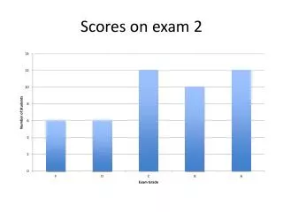
The scores for Exam 3 in Physics 2135 have been posted on the course website. You will need your PIN to access your grade. The preliminary exam average is about 68%, with scores ranging from 28 to 198. Please check your points for accuracy and submit any regrade requests by next Thursday.

E N D
Announcements • grade spreadsheets with exam 3 scores will be posted today on the Physics 2135 web site • you need your PIN to find your grade • preliminary exam average is about 68% • scores ranged from 28 to 198 will fill in the ??’s during the “live” lecture and in its “.ppt” file. • exam 3 will be returned in recitation Thursday • check that points were added correctly • regrade requests are due by next Thursday On a separate sheet of paper, explain the reason for your request. This should be based on the work shown on paper, not what was in your head. Attach to the exam and hand it to your recitation instructor by next Thursday.
Announcements Physics 2135 schedule for the rest of the semester: April 19 and 20: Lenses April 24 and 25: Double Slit Interference April 26 and 27: Thin Film Interference May 1 and 2: Diffraction May 3 and 4: Final Review Friday, May 12, 10:00am to 12:00pm 50 point all multiple choice End Material Test 200 point all problem Final Exam You may take one, or both, or neither
Today’s agenda: Death Rays. You must know when to run from Death Rays. Maybe skip for now. Refraction at Spherical Surfaces. You must be able to calculate properties of images formed by refraction at spherical surfaces. Thin Lenses: Concave and Convex Lenses, Ray Diagrams, Solving the Lens Equation. You must understand the differences between these two kinds of lenses, be able to draw ray diagrams for both kinds of lenses, and be able to solve the lens equation for both kinds of lenses. Lens Combinations, Optical Instruments. You should be aware of this useful information, which will not be presented in lecture.
Archimedes’ burning mirrors Did Archimedes use mirrors to set aflame invading Roman ships that attacked the Greek city of Syracuse in 213 BC?
Archimedes’ burning mirrors • probably a myth, BUT • it is possible under ideal condition In 2005, MIT students set wooden “ships” on fire! Details here!
Today’s agenda: Death Rays. You must know when to run from Death Rays. Refraction at Spherical Surfaces. You must be able to calculate properties of images formed by refraction at spherical surfaces. Thin Lenses: Concave and Convex Lenses, Ray Diagrams, Solving the Lens Equation. You must understand the differences between these two kinds of lenses, be able to draw ray diagrams for both kinds of lenses, and be able to solve the lens equation for both kinds of lenses. Lens Combinations, Optical Instruments. You should be aware of this useful information, which will not be presented in lecture.
Refraction at Spherical Surfaces Convex surface: 1 2 axis C F R f na nb>na Geometry: a light ray parallel to the axis passes through F.
An extended object will form an image inside the nb medium. 1 Ray 1: parallel to the axis, through F. Ray 3: through C. 2 axis R C F s f s’ na nb>na This image is real and inverted.
Concave surface: R F C axis f na nb>na Geometry: a light ray parallel to the axis seems to have come from F.
An extended object will form an image inside the na medium. Ray 1: parallel to the axis, through F. Ray 3: through C. R F C axis f na nb>na The image is virtual and upright. There are three different places to put the object. The different images formed are always virtual and upright.
We can use geometry to derive an equation relating the image and source positions, and an equation for the magnification. axis C F R s f s’ na nb
The same equations work for concave surfaces. R F C s axis s’ f na nb
Approximations Were Used! The equations in this section are excellent approximations if both the angles of incidence and refraction are small.
Recall: Sign Conventions Object Distance. When the object is on the same side as the incoming light, the object distance is positive (otherwise is negative). Image Distance. When the image is on the same side as the outgoing light, the image distance is positive (otherwise is negative). Radius of Curvature. When the center of curvature C is on the same side as the outgoing light, R is positive (otherwise is negative).
Example: a Jurassic mosquito is discovered embedded in an amber sphere which has an index of refraction of 1.6. The radius of curvature of the sphere is 3.0 mm. The mosquito is located on the principal axis and appears to be imbedded 5.0 mm into the amber. How deep is the mosquito really? nb=1 na=1.6 The object is in the amber, so na=1.6 and nb=1. R The image is in the medium from which the light radiates so s’=-5.0 mm. s s’
R is negative because it is in the medium from which the light radiates. R=-3.0 mm. nb=1 na=1.6 R s s’
Example: a Jurassic mosquito is discovered embedded in an amber sphere which has an index of refraction of 1.6. The radius of curvature of the sphere is 3.0 mm. The mosquito is located on the principal axis and appears to be imbedded 5.0 mm into the amber. What is the magnification? nb=1 na=1.6 s=4 mm and s’=-5.0 mm. na=1.6 and nb=1 R s s’
Today’s agenda: Death Rays. You must know when to run from Death Rays. Refraction at Spherical Surfaces. You must be able to calculate properties of images formed by refraction at spherical surfaces. Thin Lenses: Concave and Convex Lenses, Ray Diagrams, Solving the Lens Equation. You must understand the differences between these two kinds of lenses, be able to draw ray diagrams for both kinds of lenses, and be able to solve the lens equation for both kinds of lenses. Lens Combinations, Optical Instruments. You should be aware of this useful information, which will not be presented in lecture.
Thin Lenses Simple lens: object made of single piece of transparent material of refractive material n>1 Compound lens: device combining several simple lenses (elements) (for example, camera lens may have 6 or more elements) • simple lens has two surfaces, usually spherical • light from object incident on first surface forms image, which becomes object for second surface Thin lens: • thickness small compared to radii of curvature This would NOT qualify as a thin lens.
Converging and Diverging Lenses f f F F • converging lenses are thicker in the center • diverging lenses are thicker at the edges • there are focal points on both sides of each lens • focal length f on both sides is the same
There are two surfaces at which light refracts. Our equations (provided later) “automatically” take care of this. In your diagrams, simply draw the incident ray up to the center of the lens, then draw the refracted ray in its final direction.
Today’s agenda: Death Rays. You must know when to run from Death Rays. Refraction at Spherical Surfaces. You must be able to calculate properties of images formed by refraction at spherical surfaces. Thin Lenses: Concave and Convex Lenses, Ray Diagrams, Solving the Lens Equation. You must understand the differences between these two kinds of lenses, be able to draw ray diagrams for both kinds of lenses, and be able to solve the lens equation for both kinds of lenses. Lens Combinations, Optical Instruments. You should be aware of this useful information, which will not be presented in lecture.
Ray Diagrams for Converging Lenses Ray 1 is parallel to the axis and refracts through F. Ray 2 passes through F’ before refracting parallel to the axis. Ray 3 passes straight through the center of the lens. F I O F’ object between f and 2f: image is real, inverted, enlarged object outside of 2f: image is real, inverted, reduced object inside of f: image is virtual, upright, enlarged (see example later)
Ray Diagrams for Diverging Lenses Ray 1 is parallel to the axis and refracts as if from F. Ray 2 heads towards F’ before refracting parallel to the axis. Ray 3 passes straight through the center of the lens. F I F’ O image is always virtual, upright and reduced
Handy quick reference card from Dr. Hale: http://web.mst.edu/~hale/courses/Physics24/Quick.Reference.Cards/mirror.lens.table.pdf
Today’s agenda: Death Rays. You must know when to run from Death Rays. Refraction at Spherical Surfaces. You must be able to calculate properties of images formed by refraction at spherical surfaces. Thin Lenses: Concave and Convex Lenses, Ray Diagrams, Solving the Lens Equation. You must understand the differences between these two kinds of lenses, be able to draw ray diagrams for both kinds of lenses, and be able to solve the lens equation for both kinds of lenses. Lens Combinations, Optical Instruments. You should be aware of this useful information, which will not be presented in lecture.
The Lensmaker’s Equation • material of refractive index n embedded in air • surface 1 is surface hit by light first • radii R1 and R2 must follow sign rules, here: R1>0 and R2<0 • f>0 for converging lens, f<0 for diverging lens
Imaging equations s’ s s s’ s, s’, f, y and y’ follow same sign conventions as for mirrors
Example: an object is located 5 cm in front of a converging lens of 10 cm focal length. Find the image distance and magnification. Is the image real or virtual? It’s just a coincidence that the image is located at F’. F’ F O Image distance is 10 cm, image is on side of lens light is coming from, so image is virtual. M=2 so image is upright.
Summary of Sign Conventions Object Distance. When the object is on the same side as the incoming light, the object distance is positive (otherwise is negative). Image Distance. When the image is on the same side as the outgoing light, the image distance is positive (otherwise is negative). (negative image distance virtual image) (positive image distance real image) Radius of Curvature. When the center of curvature C is on the same side as the outgoing light, R is positive (otherwise is negative). Image height y’ is positive if the image is upright