Download

1 / 28
280 likes | 432 Vues
第五章 基本 I/O 控制 七段顯示器. 七段顯示器. 段顯示器可分為 共陽 (common anode) 共陰 (common cathode). Page 5-7 List 5.1 讓七段顯示器顯示 H. #include ht48r70a-1.INC DataBus EQU PA DataBus _ c EQU PAC DotMatrix _ SEL EQU PF0 Segment _ SEL EQU PF1 ; 7 Segment Data Bus Latch signal

E N D
七段顯示器 • 段顯示器可分為 • 共陽(common anode) • 共陰(common cathode)
Page 5-7 List 5.1 讓七段顯示器顯示H #include ht48r70a-1.INC DataBus EQU PA DataBus_c EQU PAC DotMatrix_SEL EQU PF0 Segment_SEL EQU PF1 ; 7 Segment Data Bus Latch signal start .section 'code‘ ORG 000H JMP initial ORG 010H initial: CLR PFC ;PF set to output CLR PF ;PF output 0 MOV a,10001111B MOV PDC, a ;PD.4~PD.6 is output SET PD ;PD output 1 CLR DataBus_c SET DataBus SET Segment_SEL CLR Segment_SEL ;74573 latch data CLR DataBus SET DotMatrix_SEL CLR DotMatrix_SEL ;DotMatrix latch data 00H main: MOV a,00000000B MOV PD, a CLR DataBus_c MOV a,10001001B MOV DataBus,a SET Segment_SEL CLR Segment_SEL JMP $ END
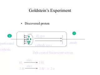
48R70A有一個外部中斷、兩個內部中斷 Timer/Event counter interrupt 中斷是利用中斷控制暫存器來控制INTC (0BH) 中斷(Interrupt)
當中斷發生且跳到相對之中斷服務程式(ISR)時 晶片自動將INTC之EMI-bit清為0,暫停所有中斷服務, 直到結束ISR程式,返回一般程式時,系統亦自動將enable EMI-bi Special location Location 000H After chip reset Location 004H External interrupt subroutine Location 008H Timer/Event 0 ISR Location 00CH Timer/Event 1 ISR
Timer1 48R70A Hardware Architecture Interrupt Timer0 Watch dog I/O Port
Timer/Event Counter • There are two 16-bit timer/event counters (計時/計數器,TMR0, TMR1) • 輸入頻率來源 • 指令週期(Instruction clock cycle) • RTC (enable only RC+RTC mode) • 外部訊號 (TMR0 pin and TMR1 pin) • 用來計數外部事件(event)出現次數 • 量測外部事件出現的寬度(time intervals or pulse widths). • 每一Timer/Event Counter 0/1有三個控制暫存器 • TMR0H, TMR0L, TMR0C / TMR1H, TMR1L, TMR1C • Write data to TMR0L only write to internal lower-order byte buffer • Write data to TMR0H will transfer the specified data and the contents of the lower-order byte buffer to TMR0H and TMR0L preload registers and load the content of preload registers to TMROH and TMROL counter register • Reading TMR0H will latch the contents of TMR0H and TMR0L counters to the destination and the lower-order byte buffer, respectively • Reading TMR0L will read the contents of the lower-order byte buffer • TMR0C is the Timer/Event Counter 0 control register
Timer 的相關問題 • 設定Timer0之初值為0xabcd • MOV TMR0L, 0x cd 將0xcd放到 low byte buffer • MOV TMR0H, 0x ab 將0xab放到preload register的high-byte, 將low byte buffer 放到preload register的low byte preload register的值放到Timer0 Counter • 當Timer0 Overflow時, 會自動將 preload register的值放到Timer0 Counter • 讀取Timer0之內容 • MOV MEM[x], TMR0H 將Timer0 Counter的high-byte放到MEM[x], Low-byte放到Low byte buffer • MOV MEM[y], TMR0L將Low byte buffer 的值放到MEM[y]
TM0, TM1 define the operation mode • Event count mode (external clock) • Clock source comes from TMR0 pin • Timer mode (internal clock) • Clock source comes from fsys/4 or RTC (decision by ROM option) • Pulse width measurement mode • Count the high or low level duration of the external signal TMR0 pin (decision by TE-bit of TMR0C) • The counting frequency is based on the fsys/4 or RTC (decision by ROM option) • In the event or timer mode, the counter will count from the current contents in the counter to FFFFH. • Once overflow occurs, the counter is reloaded from the preload register and generate interrupt request flag • In the high/low pulse width measurement mode and TON and TE bit are set to 1, the counter will begin counting when the TMR0 pin in the transient from high to low level • The counter will stop when the TMR0 pin returns to the original level and reset the TON
若供即Timer0的頻率為32768, 現希望每0.5秒 中產生中斷一次 x為Timer0需計數的次數 所以Timer0的初值應為65536-16384=49152=0xC000 mov TMR0L, 00h (mov a, 00h mov TMR0L, a) mov TMROH, C0h mov TMR0C, 90H Timer初值的決定
EX:反應計時器 • 反應計時器可測量一個人對視覺或聽覺刺激反應所需要的時間,上例中, 應用程式Delay random時間後,點亮一顆LED,而當受測者按下反應按鈕所需的時間顯示於七段顯示器上
5.3 一位元上數計數器 • 利用TMR0 來計時, 設定每1 ms, TMR0產生1次中斷 • 因fsys = 4 MHz 指令週期為 1MHz 1us • 因此TMR0 每計數1000次代表1ms • 即設定TMR0 為 65535-1000 • TMR0L = low (65535-1000) • TMR0H = high (65535-1000) • 每一秒, 七段顯示器的內容加1 • 中斷1000次表示1秒
設定interrupt vector Page 5-15 start .section 'code' ORG 000H JMP initial ORG 008H JMP timer0_ISP ORG 010H initial: CLR Seg_HaveAdd CLR Seg_CountData CLR PFC ;PF.1 Segment_SEL CLR PF . . .
Page 5-16 TMR0 中斷服務副程式 Save acc與status暫存器 timer0_ISP PROC MOV a_save,a MOV a,STATUS MOV STATUS_save_timer0,a SDZ Seg_CountAddTime_L JMP out_timer0_ISP SDZ Seg_CountAddTime_H JMP out_timer0_ISP MOV a,Seg_CountAddBaseTime_L MOV Seg_CountAddTime_L,a MOV a,Seg_CountAddBaseTime_H MOV Seg_CountAddTime_H,a SET Seg_HaveAdd out_timer0_ISP: MOV a,STATUS_save_timer0 MOV STATUS,a MOV a,a_save RETI timer0_ISP ENDP 判斷是否中斷1000次 若中斷1000次, 將1000重存回 變數 (Seg_CountAddTime_L Seg_CountAddTime_H), 且將旗標Seg_HaveAdd設為1,
ROM 的任何址方皆可用來存放look-up tables Holtek提供2個指令用來查表 TABRDC [m] Read current page TABRDL [m] Read last page The location of the table read is pointed by the register TBLP (mem[07H]) Low-byte of the table is stored in memory [m] High-byte of the table is stored in register TBLH (08H) 查表指令 PC MOV A,1 MOV TBLP,A TABRDL [60h] ORG LASTPAGE Table: dc 3135h dc1234h What are the values of Mem[60h] and TBLH ?
範例:查表指令 (TABRDC) Port A接8顆LED, 做LED顯示變化 MAIN: MOV A, TABL MOV TBLP, A MOV A,06 MOV COUNT, A LOOP: TABRDC PA CALL DELAY INC TBLP SDZ COUNT JMP LOOP JMP MAIN TABL: DC 0000000010000001B DC 0000000001000010B DC 0000000000100100B DC 0000000000011000B DC 0000000000100100B DC 0000000001000010B
範例:查表指令 (TABRDL) 與前例同, 將Current page table改成last page table MAIN: MOV A, 0 MOV TBLP, A MOV A,06 MOV COUNT, A LOOP: TABRDL PA CALL DELAY INC TBLP SDZ COUNT JMP LOOP JMP MAIN ORG LASTPAGE TABL: DC 0000000010000001B DC 0000000001000010B DC 0000000000100100B DC 0000000000011000B DC 0000000000100100B DC 0000000001000010B
Page 5-17 ORG LASTPAGE Segment_table: ; pgfedcba DC 11000000B ;0 DC 11111001B ;1 DC 10100100B ;2 DC 10110000B ;3 DC 10011001B ;4 DC 10010010B ;5 DC 10000010B ;6 DC 11111000B ;7 DC 10000000B ;8 DC 10010000B ;9 main: SNZ Seg_HaveAdd JMP $-1 CLR Seg_HaveAdd INC Seg_CountData MOV a,10 SUB a,Seg_CountData SZ Z CLR Seg_CountData MOV a,00000000B MOV PD,a MOV a,Seg_CountData MOV TBLP,a CLR DataBus_c TABRDL DataBus SET Segment_SEL CLR Segment_SEL JMP main
5.4 四位元掃描顯示上數計數器 • 靜態方式驅動七段顯示器
8-bit 輸出埠 緩衝器 8-bit 微控制器 +5v +5v 輸出埠 共陽極七段顯示器多工掃描 多顆七段顯示器的驅動方式 • 多工掃描驅動七段顯示器 • 利用人類眼睛視覺暫留現象 • 讓多顆七段顯示器輪流顯示 • 若輪流顯示的速度夠快的話,快到讓人眼睛不會感覺到閃爍現象(通常以50Hz以上的輪流顯示速度來驅動),則感覺上即是每一顆七段顯示器皆同時在顯示
由於人類之視覺暫留約為1/16秒 ~ 1/24秒,依經驗值將其取為1/50秒,即掃描頻率為50次/秒,故每隔1/50秒 = 20 ms即要掃描一次,若有6顆七段顯示器,故每一顆七段顯示器之顯示時間約為20/6 = 3.3 ms,可以取3 ms為七段顯示器之on時間。請注意:在掃描過程中,每個七段顯示器間必須有數十微秒的關閉時間(off time)以防止七段顯示器顯示時產生殘影。
5.4 四位元掃描顯示上數計數器 • 利用TMR0 來計時, 設定每1 ms, TMR0產生1次中斷 • 以掃描方式將4 位數之上數計數器(0000~9999)顯示於四顆七段顯示器上 • 每一秒, 七段顯示器的內容加1 • 中斷1000次表示1秒 • 每3ms, 移動掃描顯示 • 中斷3次即移動1次