Download
1 / 20
210 likes | 349 Vues
Experimental Evaluation of System-Level Supervisory Approach for SEFIs Mitigation. Mrs. Shazia Maqbool and Dr. Craig I Underwood. 1. Maqbool. MAPLD 2005/P181. Overview. Context Motivation Mitigation Scheme Top Level Description Protocol Gets Defined Test Bed

E N D
Experimental Evaluation of System-Level Supervisory Approach for SEFIs Mitigation Mrs. Shazia Maqbool and Dr. Craig I Underwood 1 Maqbool MAPLD 2005/P181
Overview • Context • Motivation • Mitigation Scheme • Top Level Description • Protocol Gets Defined • Test Bed • Experimental Results • Conclusions 2 Maqbool MAPLD 2005/P181
Single Event Functional Interrupts (SEFIs) • A type of anomaly in microcircuits caused by a single ion strike • Occurs in sensitive cross-section of the device • User doesn’t have direct access to fault location • Signatures • An upset rate higher than expected • Non responding device • In a communication network SEFI is an event, which stops communication • Variations in device current consumption • During a SEFI, device is unavailable to the system • Device is potentially recoverable • Recovery involves resetting or power cycling • System recovery requires restoring the device functionality followed by its state recovery 3 Maqbool MAPLD 2005/P181
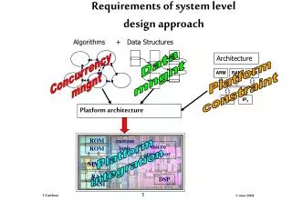
Mitigation Levels Using Radiation Hardening Processes Device Level Built in Fault Tolerance Features Incorporating Redundancy within Device Error Detection And Corrections (EDACs) Redundancy Techniques, e.g. Voting, Lockstep etc. Unit Level Configuration Scrubbing System/Architectural Level Data Handling Networks 4 Maqbool MAPLD 2005/P181
Motivation • Space applications demand: • but less… • Mass, volume and power budget • Cost • Development time • more… • Computational power • Standardization • Reusability • Candidate architectures are heavily based on state-of-the-art COTS technology • Reliability • Availability • SEFIs and single event transients are becoming dominant radiation hazards • A unit level approach has usually been considered for SEFI mitigation 5 Maqbool MAPLD 2005/P181
System Architecture • A fast data network interlinks all units • Scalable • Distributed • Reusable • A system level SEFI mitigation • A diagnosis and recovery (DAR) packet from each unit acts as an indicator of health status for the unit • The supervisor intervenes when a packet does not arrive or it does not match expectation 6 Maqbool MAPLD 2005/P181
Why a System-Level Approach • Cost-effective • Adaptable • Reusable • Power cycling requirements associated with SEFIs, demands for an external entity to hold state data and to initiate a recovery procedure • In case of a permanent failure, it can be switched off • Supervisory functions, network and configuration management can be combined 7 Maqbool MAPLD 2005/P181
Possible sources of fault Processor Memory Network interface Processor Interface FPGA EDAC OPC Memory The OBC Subsystem On-Board Computer • Required underlying mitigations • EDAC • OPC Over-Current Protection Circuitry (OPC) 8 Maqbool MAPLD 2005/P181
SEFI Signatures 9 Maqbool MAPLD 2005/P181
System ID Length Flags Diagnostic health data/Screech data Supervisory Protocol • Two Types of packets • Screech Packet • Diagnosis And Recovery (DAR) Packet • DAR task • Perform Testing of the Processor • Collects error count of the memory unit • Updates state data • Current consumption of the OBC module will be monitored 10 Maqbool MAPLD 2005/P181
OBC-Processor OBC- Interface FPGA Supervisor Code Store DAR Process Starts Disable Interrupts Diagnosis And Recovery (DAR) Packet Flow Perform Test SODARP Marker Start Sampling Current Enable Interrupts Collect SEU Count Send DAR Packet Waiting for Supervisor Response Collect Current Value DAR Packet Received Compare with Stored Values Command to Update Program Memory Update Memory 11 Maqbool MAPLD 2005/P181
Fault Type Recovery Procedure Screech Reloadprogram memory Packet time-out (Network problems) Next Slide Packet time_out (Processor Problem) Next Slide Current consumption variations Power cycle and reload memory SEU count exceeding threshold Reload memory Test task result mismatch Reset and reload memory Recovery Method 12 Maqbool MAPLD 2005/P181
Recovery Method (2) • In case of a processor reset and power cycle, the OBC should be allowed sufficient time for reinitialization • The supervisor needs to keep a record of recoveries applied • Consecutive recovery cycles needs to be avoided 13 Maqbool MAPLD 2005/P181
Test Bed • Demonstration of the synchronization protocol • PC1 executes the OBC program • PC2 executes the supervisor program Synchronization Scheme 1 Synchronization Scheme 2 14 Maqbool MAPLD 2005/P181
Parallel Port Ethernet UDP/IP Packet from the supervisor RC 203 board passes it as it is to the OBC-program Parallel Port Ethernet UDP/IP Packet from the supervisor RC 203 passes only data bytes Packet on Ethernet Parallel Port OBC program receives a packet, checks source, if it is from the supervisor program, it sends a packet to the FPGA FPGA sends the packet to the supervisor program on Ethernet Configuration 1 Packet on Ethernet Parallel Port OBC program receives data, it sends data bytes to the FPGA FPGA encodes received data into UDP/IP packet Configuration 2 Synchronization Scheme 1 15 Maqbool MAPLD 2005/P181
Time Measurement Method • The ethereal graphical user interface (GUI) network protocol analyzer was used • It displays time when a packet was captured • It also displays IP source and destination, protocol type source and destination port for all captured packets. • Selecting a packet from the list of captured packets shows total bytes captured on the network medium, Ethernet source and destination addresses, and number of data bytes in the packet. • Time was measured from the moment it captures packet sent by the supervisor to the point when it captures a return packet from the OBC for synchronization scheme 1. • For synchronization scheme 2, time was measured between two consecutive packets from the OBC. 16 Maqbool MAPLD 2005/P181
Data bytes Average time between two packets in a pair (Supervisor packet and OBC packet in response) (ms) Time required for 1 byte to travel through the system Time measured in n run with N bytes – time measured in n+1 run with N+K bytes divided by K (s) 18 101.053 101.264-101.053/18 = 11.7 36 101.264 101.822-101.264/36 = 15.5 72 101.822 102.229-101.822/28 = 14.53 100 102.229 103.677-102.229/400 = 14.85 500 103.677 Results (1) 17 Maqbool MAPLD 2005/P181
Data bytes Experiment Time measured between a supervisor packet and a response packet from the OBC (s) 18 Configuration 1 with RC200GetBlockStall function 101053 18 Configuration 1 with RC200GetBlock function 1201 18 Configuration 2 with RC200GetBlockStall function 101066 18 Ping program 270 Results (2) 18 Maqbool MAPLD 2005/P181
Experiment Time measured Synchronization scheme 2: Time measured between two consecutive packets from OBC (18 data bytes) 261 s Synchronization scheme 1: OBC program crashed and reinitialized manually FPGA cleared using FTU facility and OBC program reinitialized manually Time between last OBC packet prior to fault and first packet after recovery 12 s, 299 ms and 644 s 15 s, 339ms and 501 s Synchronization scheme 2: OBC program crashed and reinitialized manually FPGA cleared using FTU facility and OBC program reinitialized manually Time between last OBC packet prior to fault and first packet after recovery 11 s, 316 ms and 272 s 14 s, 971ms and 559 s Parallel Port OBC sends data bytes to the interface FPGA Interface FPGA encodes data into UDP/IP packet and writes it on Ethernet Ethernet Configuration for Synchronization Scheme 2 Synchronization Scheme 2 19 Maqbool MAPLD 2005/P181
Conclusions A system-level approach has been presented to mitigate SEFIs in data handling architectures • Upset detection is not straightforward, limits effectiveness of currently available mitigation techniques • Increasing SEFI susceptibility in all major data handling device technologies • A system level intelligent supervisor allows monitoring of a wide range of devices with minimal overhead • Synchronization is straightforward • Two synchronization schemes have been demonstrated • Few simple experiments were performed to establish a time-out period for a packet from the OBC. • Once this information was achieved, the system behaved as expected and a synchronized packet communication was established between the OBC and the supervisor programs • In event of a SEFI, the supervisor program needs to wait until the OBC program is up again. Time-out for this wait period will depend on the recovery latency 20 Maqbool MAPLD 2005/P181