Download
1 / 32
320 likes | 325 Vues
More On Crystal Diffraction Including a Survey of Various X-Ray Camera Set-Ups. Types of X-ray C amera s.

E N D
More On Crystal Diffraction Including a Survey of Various X-Ray Camera Set-Ups
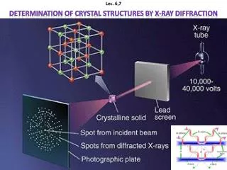
Types of X-ray Cameras There are many types of X-ray camera to sort out reflections from different crystal planes. We will briefly look at 3 types of X-ray photograph that are widely used for the simple structures. 1. Laue photograph 2. Rotating crystal method 3. Powder photograph
Laue Method • The Laue method is mainly used to determine the orientation of large single crystals while radiation is reflected from, or transmitted through a fixed crystal. • The diffracted beams form arrays of spots, that lie on curves on the film. • The Bragg angle is fixed for every set of planes in the crystal. Each set of planes picks out and diffracts the particular wavelength from the white radiation that satisfies the Bragg lawfor the values of d and θ involved.
Back-Reflection Laue Method • In the back-reflection method, the film is placed between the x-ray source and the crystal. The beams which are diffracted in a backward direction are recorded. • One side of the cone of Laue reflections is defined by the transmitted beam. • The film intersects the cone, with the diffraction spots generally lying on a hyperbola. Single Crystal Film X-Ray
Transmission Laue Method • In the transmission Laue method, the film is placed behind the crystal to record beams which are transmitted through the crystal. • One side of the cone of Laue reflections is defined by the transmitted beam. The film intersects the cone, with the diffraction spots generally lying on an ellipse Single Crystal Film X-Ray
LauePatterns • The symmetry of the Laue spot pattern reflects the symmetry of the crystal when viewed along the direction of the incident beam. Laue method is often used to determine the orientation of single crystals by illuminating the crystal with a continous spectrum of X-Rays. Single crystals Continous spectrum of X-Rays Symmetry & orientation of crystals
Crystal Structure Determination by the Laue Method • The Laue method is mainly used to determine the crystal orientation. • Although the Laue method can also be used to determine the crystal structure, several wavelengths can reflect in different orders from the same set of planes, with the different order reflections superimposed on the same spot in the film. This makes crystal structure determination by spot intensity diffucult. • The rotating crystal method overcomes this problem.
Rotatıng Crystal Method • In the rotating crystal method, a single crystalis mounted with an axis normal to amonochromatic x-ray beam.A cylindrical film is placed around it & thecrystal is rotated about the chosen axis. • As the crystal rotates, sets of lattice planes will at some point make the correct Bragg angle for the monochromatic incident beam,and at that point a diffracted beam will be formed.
Rotatıng Crystal Method The Lattice constant of the crystal can be determined with this method. For a given wavelengthλ if the angleθat which areflection occurs is known, dcan be determined by using Bragg’s Law.
Film Rotatıng Crystal Method The reflected beams are located on the surfaces of imaginary cones. By recording the diffraction patterns (both angles & intensities) for various crystal orientations,one can determine the shape &size of unit cell as well as the arrangement of atomsinside the cell.
The PowderMethod • If a powdered crystal is usedinstead of a single crystal, then there is no need to rotateit, because there will always be some small crystals at an orientation for which diffraction is permitted. Here a monochromatic X-ray beam is incident on a powdered or polycrystalline sample. • Useful for samples that are difficult to obtain in single crystal form. • The powder method is used to determine the lattice parameters accurately. Lattice parameters are the magnitudes of the unit vectors a, b and c which define the unit cell for the crystal. • For every set of crystal planes, by chance, one or morecrystals will be in the correct orientation to give the correct Bragg angle to satisfy Bragg's equation. Every crystal plane is thus capable of diffraction. • Each diffraction line is made up of a large number of small spots, each from a separate crystal. Each spot is so small as to give the appearance of a continuous line.
The PowderMethod • If a monochromatic X-ray beam is directed at a single crystal, then only one or two diffracted beams may result. See figure • For a sample of several randomly orientated single crystals, the diffracted beams will lie on the surface of several cones. The cones may emerge in all directions, forwards and backwards. See figure • For a sample of hundreds of crystals (powdered sample), the diffracted beams form continuous cones. A circle of film is used to record the diffraction pattern as shown. Each cone intersects the film giving diffraction lines. The lines are seen as arcs on the film. See figure:
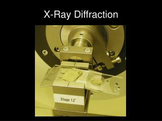
Debye Scherrer Camera • A small amount of powdered material is sealed into a fine capillary tube made from glass that does not diffract X-Rays. • The sample is placed in the Debye Scherrer camera and is accurately aligned to be in the center of the camera. X-Raysenter the camera through a collimator. • The powder diffracts the X-Rays in accordance with Braggs Law to produce cones of diffracted beams. These cones intersect a strip of photographic film located in the cylindrical camera to produce a characteristic set of arcs on the film.
Powder Diffraction Film • When the film is removed from the camera, flattened and processed, it shows the diffraction lines and the holes for the incident and transmitted beams.
Some Typical Measurement Results • Laue - “white” x-rays • Yields stereoscopic projection of reciprocal lattice • Rotating-Crystal method - monochromatic x-rays • Fix source and rotate crystal to reveal reciprocal lattice • Powder diffraction - monochromatic x-rays • Powder sample to reveal “all” directions of RL
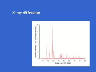
(a)Diagram of a diffractometer, showing powder sample, incident & diffracted beams. (b)Diffraction Pattern from a sample of gold powder.
Example (From the Internet) The results of a diffraction experiment using X-Rays with λ = 0.7107 Å(radiation obtained from a molybdenum, Mo, target) show that diffracted peaks occur at the following 2θ angles: Find the crystal structure, the indices of the plane producing each peak, and the lattice parameter of the material.
Example (Solution) First calculate the sin2 θ value for each peak, then divide through by the lowest denominator, 0.0308.
This is the lattice parameter for body-centered cubic iron. Example (Solution Continued) Then use the 2θ values for any of the peaks to calculate the interplanar spacing & thus the lattice parameter. Picking peak 8: 2θ = 59.42° or θ = 29.71° So, for example: Ǻ Ǻ
Measurement Results XRD Pattern forNaCl XRD Pattern forKCl
Applications of XRD XRD is a nondestructive technique. Some of uses of X-Ray Diffraction are: • Distinguishing between crystalline & amorphous materials. • Determination of the structure of crystalline materials. • Determination of electron distribution within the atoms,& throughout the unit cell. • Determination of the orientation of single crystals. • Determination of the texture of polygrained materials. • Measurement of strain and small grain size…..etc.
Advantages & Disadvantages of X-Ray Diffraction Compared to Other Methods Advantages • X-Raysare the least expensive, the most convenient &the most widely used method to determine crystal structures. • X-Rays are not absorbed very much by air, so the sample need not be in an evacuated chamber. Disadvantages • X-Rays do not interact very strongly with lighter elements.
Diffraction Methods • Other radiation sources than X-Rays, such as neutrons or electrons can also be used in crystal diffraction experiments. • The physical basis for the diffraction of electrons orneutrons is the same as that for the diffraction of X Rays. The only difference is in the mechanism of scattering.
Neutron Diffraction • Neutrons were discovered in 1932 & their (de-Broglie) wave properties were proven in 1936. Energy: E = (p2)/(2mn), Momentum: p = (h/λ) λ=Wavelength, mn=Mass = 1.67× 10⁻²⁷ kg • Wavelengths needed for crystal diffraction are of the order λ ~1Ǻ • So this gives needed neutron energies of E ~ 0.08 eV This is of the same order of magnitude as the thermal energyat room temperature,kT ~ 0.025 eV.For this reason,these are called thermal neutrons.
Neutron Diffractionhas several advantages over X-Ray Diffraction. • It is an important tool in the investigation of the magnetic ordering that occurs in some materials. • Light atoms such as H are better resolved in aneutron pattern because, having only a few electrons to scatter the X-Rays, they do not contribute significantly to anX-Ray diffraction pattern.
Because they are neutral,neutrons do not interact with electrons in the crystal. So, unlike X-Rays, which are scattered entirely by electrons, neutrons are scattered entirely by nuclei. • Although uncharged, neutrons havean intrinsic magnetic moment, so they will interact strongly with atoms & ions in the crystal which also have a magnetic moment. • Neutrons are more useful than X-rays for determining the crystal structures of solids containing light elements. • Neutron sources in the world are limited so neutron diffraction is a very special tool & is very expensive.
Typical Neutron Diffraction Data 1.16 Ǻ Neutrons on CaF2
Electron Diffraction For • Electron Diffractionhas also been used in the analysis of crystal structure. The electron, like the neutron, possesses wave-like properties: • Of course, electrons are charged & so interact strongly with all atoms. So electrons with an energy of a few eV are completely absorbed by the crystal. In order to enable an electron beam to penetrate into a crystal, it must have a very high energy (50 keV to 1MeV). Inaddition, the crystal must be thin (100-1000 nm). • If low electron energies are used, the penetration depth will be very small (only about 50 Ǻ), and the beam will be reflected from the surface.Consequently, electron diffraction is a useful technique for surface structure studies. • Electrons are scattered strongly in air, so diffraction experiments must be carried out high vacuum. This brings complication and it is expensive as well.